Shoe for expandable liner system and method

a liner system and expandable technology, applied in the direction of drilling casings, drilling pipes, borehole/well accessories, etc., can solve the problems of requiring significant amounts of time and creating an associated cos

Active Publication Date: 2007-07-10
BAKER HUGHES INC
View PDF10 Cites 23 Cited by
  • Summary
  • Abstract
  • Description
  • Claims
  • Application Information

AI Technical Summary

Benefits of technology

[0005]An apparatus to protect the mounting area of casing when subsequently attaching a tubular is disclosed. A sleeve that defines a sealed cavity having a loose incompressible material inside covers the mounting location on the casing. The cementing of the casing takes place through the sleeve. After the cementing, the sleeve is drilled out and the incompressible material is removed to the surface with the drill cuttings. A tubular is inserted in the casing and is preferably expanded into sealing contact with the mounting location on the casing. At the end of expansion, the run in shoe on the tubular is retrieved.

Problems solved by technology

However these techniques require significant amounts of time and create an associated cost.

Method used


Image

  • Shoe for expandable liner system and method
  • Shoe for expandable liner system and method
  • Shoe for expandable liner system and method

Examples


Embodiment Construction

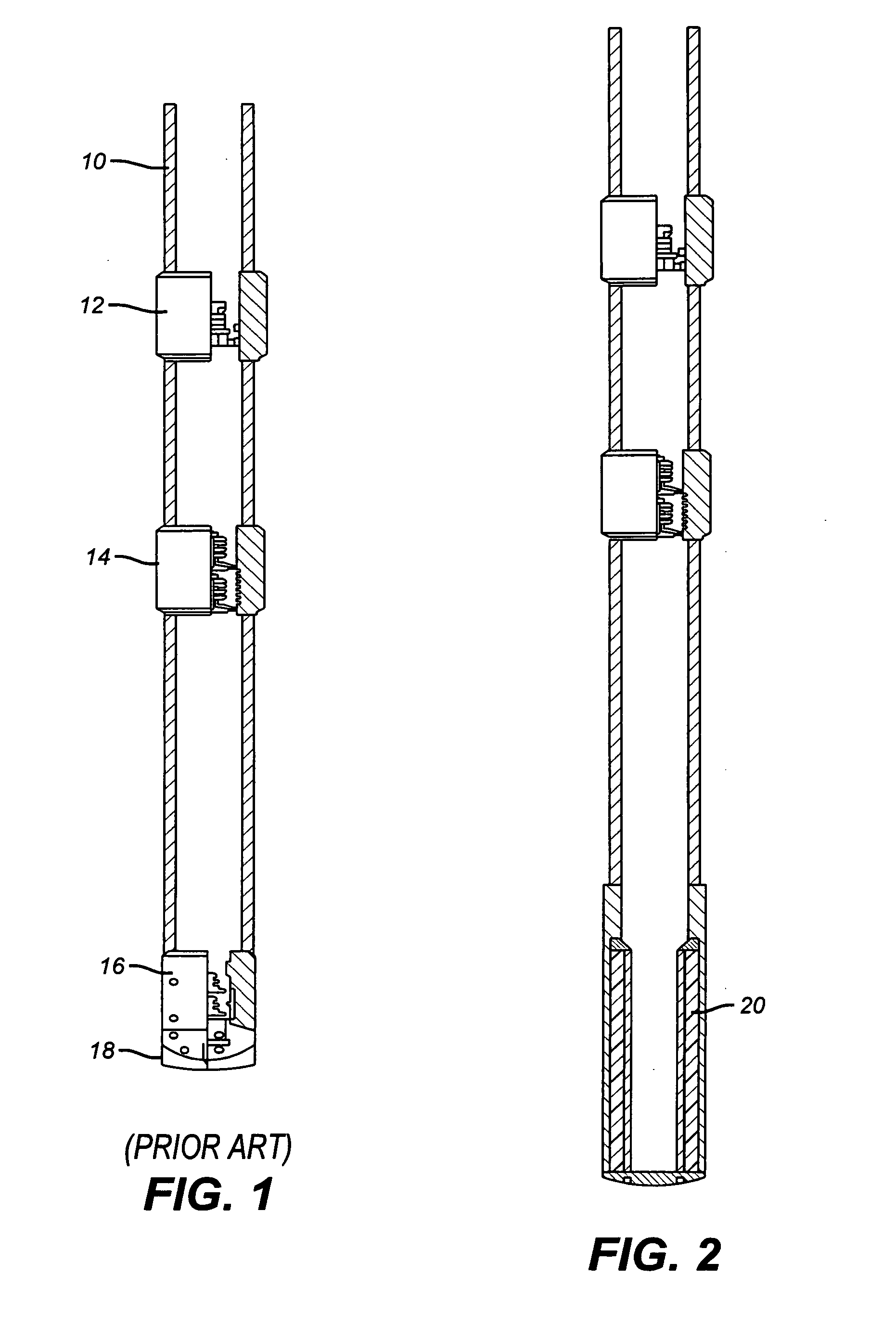
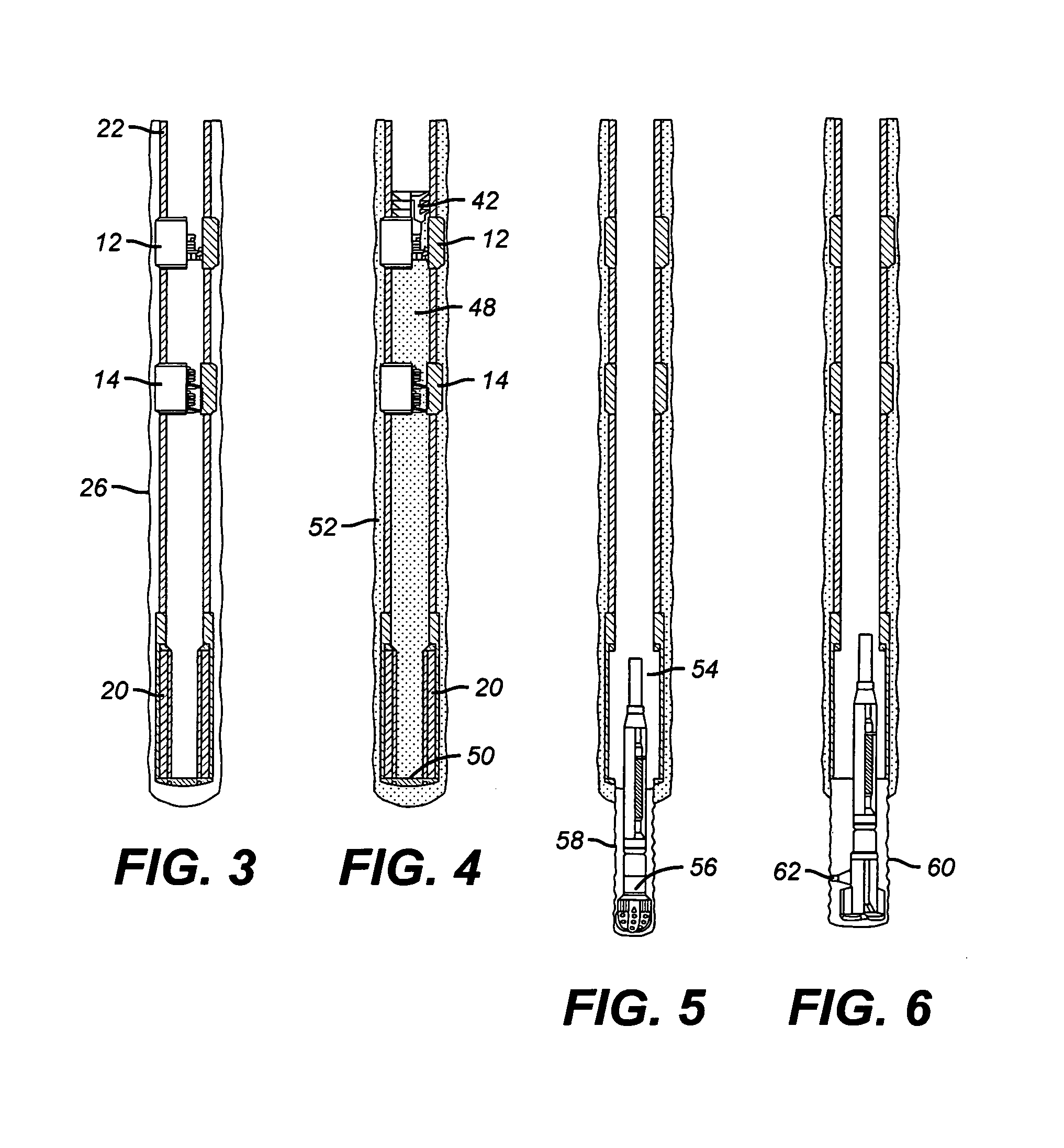
[0025]FIG. 1 illustrates a production casing 10 having a known landing collar 12 and a standard float collar 14 as well as a casing shoe 16 adjacent its lower end 18. Typically, in the past, the cement is pumped through the casing shoe 16 and then a dart or wiper is used to displace cement from the casing 10 and out through the shoe 16 and into the surrounding annulus. When the well is to be drilled deeper, the shoe 16 is drilled out but residual cement could still be present. The presence of such cement or shoe debris after drilling can affect the seal that is subsequently needed when a liner is inserted and secured to the casing 10. This is particularly a concern when the liner is to be expanded to secure it to the casing 10.

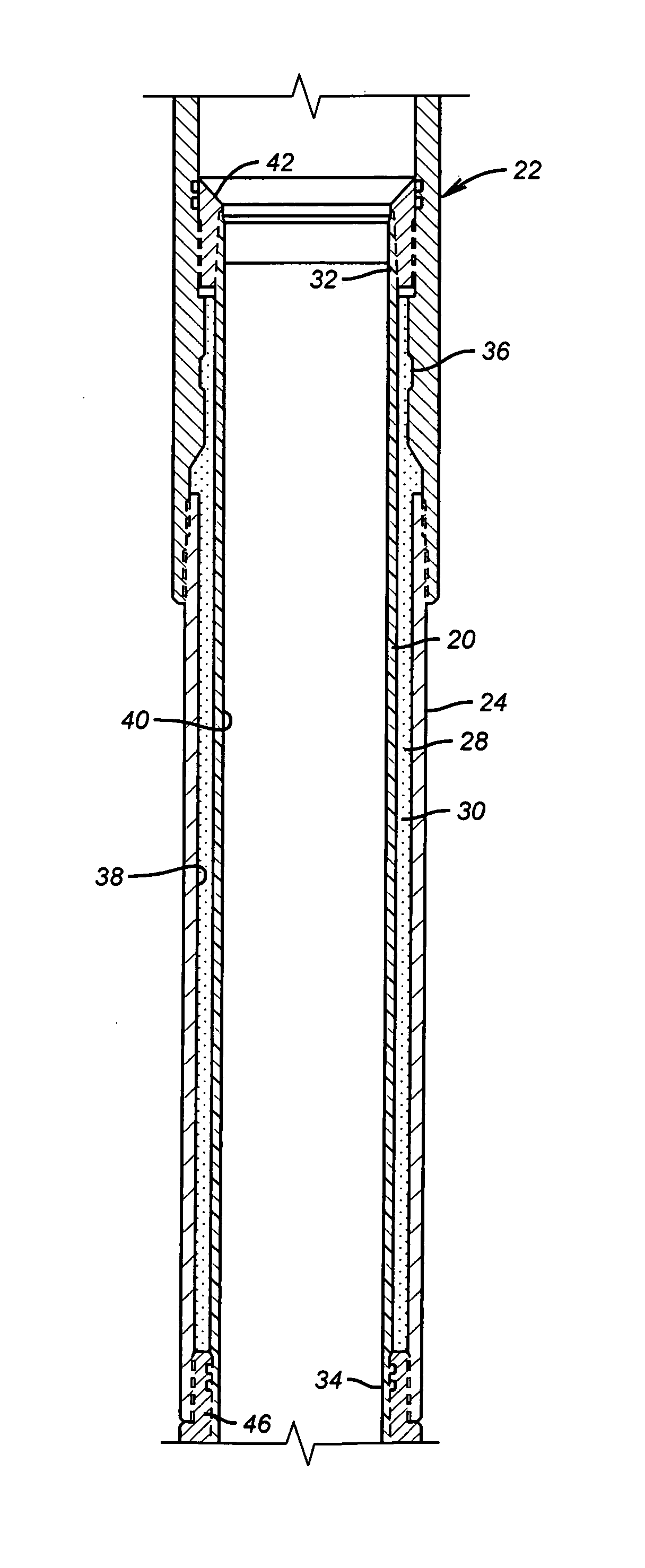
[0026]The present invention addresses this concern with a sleeve 20 shown in FIGS. 2 and 15. As shown in FIG. 15, the production casing 22 has a lower section 24. Inside section 24 is a sleeve 20 mounted preferably concentrically and defining an annular space ...


PUM


Abstract

An apparatus to protect the mounting area of casing when subsequently attaching a tubular is disclosed. A sleeve that defines a sealed cavity having a loose incompressible material inside covers the mounting location on the casing. The cementing of the casing takes place through the sleeve. After the cementing, the sleeve is drilled out and the incompressible material is removed to the surface with the drill cuttings. A tubular is inserted in the casing and is preferably expanded into sealing contact with the mounting location on the casing. At the end of expansion, the run in shoe on the tubular is retrieved.

Description

PRIORITY INFORMATION[0001]This application claims the benefit of U.S. Provisional Application No. 60 / 444,816 on Feb. 4, 2003.FIELD OF THE INVENTION[0002]The field of this invention is the method of running a tubular inside casing and securing it and more particularly to techniques for protecting the mounting location for the tubular on the casing as the casing is cemented.BACKGROUND OF THE INVENTION[0003]FIG. 1 is illustrative of the prior techniques of running in casing with a casing shoe 16 near its lower end. If later a tubular is run in and needs to be attached to the casing by expansion, the presence of cement debris in the support area on the casing where the tubular will be attached could prevent a sealed connection from being obtained. One way around that would be to deliver the cement into a shoe mounted below the point at which the liner will be attached later. Another method would be to run brushes and scrapers into the mounting location after cementing to be sure it was ...

Claims


Application Information

Patent Timeline
Patent Type & Authority Patents(United States)
IPC IPC(8): E21B23/01E21B17/10E21B33/14E21B43/10
CPCE21B17/1007E21B43/103E21B33/14E21B17/14
Inventor CARMODY, MICHAEL A.JABS, MATTHEW J.PAYNE, HAROLD E.ADAM, MARK K.
Owner BAKER HUGHES INC
Why Eureka
Try Eureka