Method for analyzing drill cuttings using nuclear magnetic resonance techniques

a nuclear magnetic resonance and cutting technology, applied in the field of petrophysical properties evaluation of earth formations, can solve the problems of formation evaluation while drilling technology is relatively expensive, application requires a high degree of well stability, and the methods known in the art have a number of limitations

Inactive Publication Date: 2006-12-07
YU GANG +4
View PDF2 Cites 43 Cited by
  • Summary
  • Abstract
  • Description
  • Claims
  • Application Information

AI Technical Summary

Problems solved by technology

The above methods known in the art have a number of limitations.
Formation evaluation while drilling technologies are relatively expensive and their application requires a high degree of well stability.
Interpretation of the results frequently includes operational noise from the drilling process.
First, it is difficult to use only one type of measurement to determine the generally required petrophysical parameters, these parameters including fractional volume of pore space in a reservoir formation (porosity), and permeability, that is, the quantitative determination of filtration capacity properties (FCP) require a set of different tools (Santarelli, 1998; Marsala et al., 1977; Nes et al, 1998).
It has also proven to take too long to provide quantitative on-line information during drilling on well site.
However, advanced mud logging at the well site is labor intensive, and thus expensive, and can be applied generally to drill cuttings having particle sizes of more than 3 mm.
The difficulties of measurements using high field NMR spectrometers, namely the high radio frequency, and difficulty of handling the large size of high field instruments discouraged wider use of this technology at the well site.
However, the processes used on coarse cuttings have not proven effective for determining petrophysical parameters on fine and middle size cuttings.

Method used


Image

  • Method for analyzing drill cuttings using nuclear magnetic resonance techniques
  • Method for analyzing drill cuttings using nuclear magnetic resonance techniques
  • Method for analyzing drill cuttings using nuclear magnetic resonance techniques

Examples


Embodiment Construction

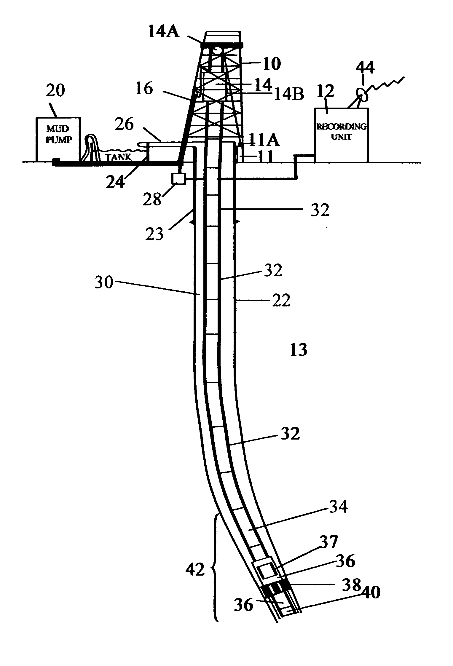
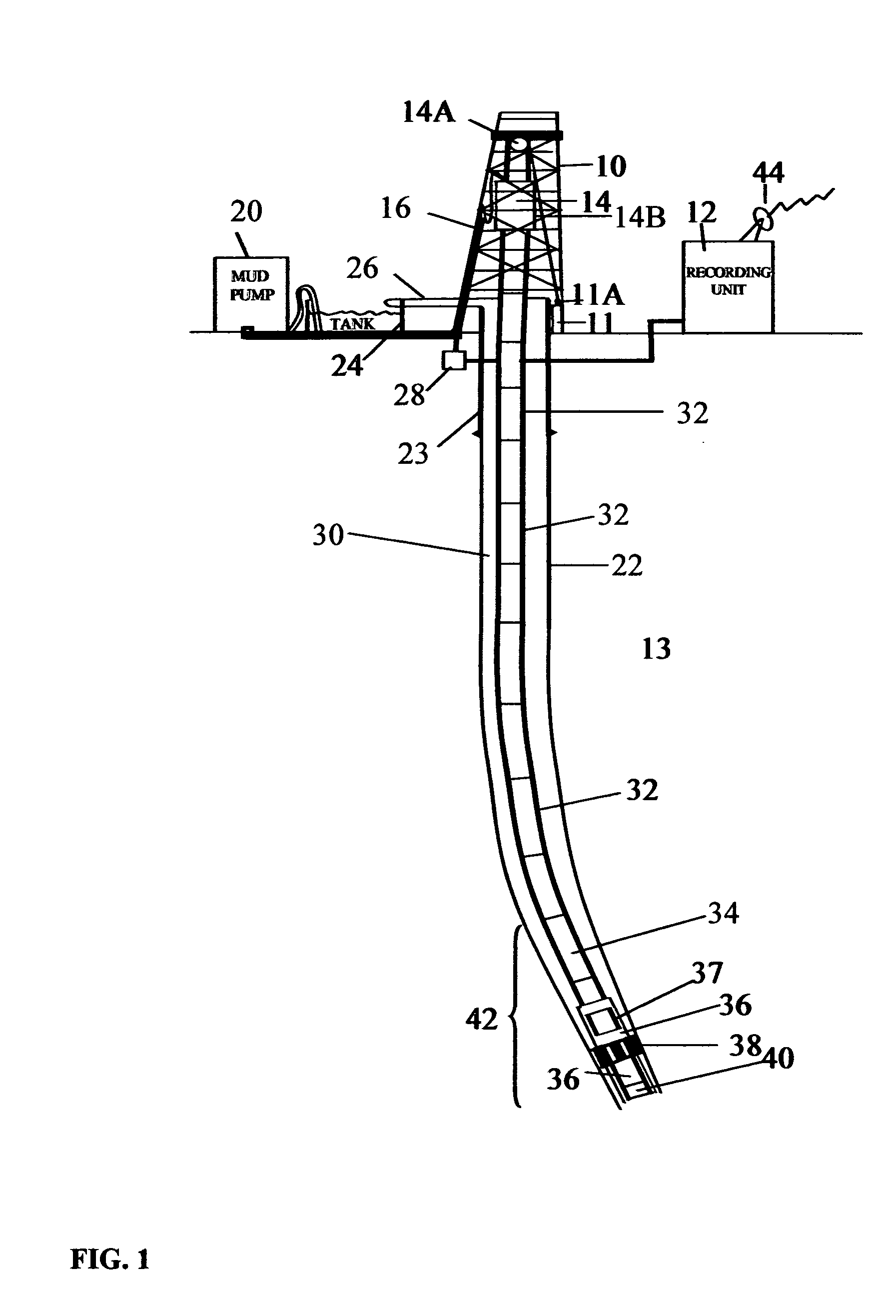
[0032]FIG. 1 shows a typical wellbore drilling system which may be used with various embodiments of the invention. In FIG. 1, a drilling rig 10 includes a drawworks 11 or similar lifting device known in the art to raise, suspend and lower a drill string. The drill string includes a number of threadedly coupled sections of drill pipe, shown generally at 32. A lowermost part of the drill string is known as a bottom hole assembly (“BHA”) 42, which includes, in the embodiment of FIG. 1, a drill bit 40 to cut through earth formations 13 below the earth's surface. The BHA 42 may include various devices such as heavy weight drill pipe 34, and drill collars 36. The BHA 42 may also include one or more stabilizers 38 that include blades thereon adapted to keep the BHA 42 roughly in the center of the wellbore 22 during drilling. In various embodiments, one or more of the drill collars 36 may include a measurement while drilling (“MWD”) sensor and telemetry unit (collectively “MWD system”), sho...


PUM


Abstract

A method for evaluating permeability of Earth formations includes determining a transverse nuclear magnetic relaxation spectrum by performing a nuclear magnetic resonance experiment directly on drill cuttings of the Earth formation removed from a wellbore, and estimating permeability from the transverse nuclear magnetic relaxation spectrum.

Description

CROSS-REFERENCE TO RELATED APPLICATIONS [0001] Not applicable. STATEMENT REGARDING FEDERALLY SPONSORED RESEARCH OR DEVELOPMENT [0002] Not applicable. BACKGROUND OF INVENTION [0003] 1. Field of the Invention [0004] The invention relates generally to the field of evaluation of petrophysical properties of Earth formations. More specifically, the invention relates to methods for evaluating petrophysical properties of Earth formations using samples of drill cuttings and using nuclear magnetic resonance (NMR) measurement and analysis methods. [0005] 2. Background Art [0006] Faster drilling and higher drilling cost (especially offshore) dictate reducing cost and decreasing the time required for well evaluation. Simultaneously, it is necessary to ensure the reliability of the results of such evaluation. This is especially important for Earth formation reservoirs that include complicated geology and that may involve long exploitation time, because the in-situ oil viscosity can be different i...

Claims


Application Information

Patent Timeline
Patent Type & Authority Applications(United States)
IPC IPC(8): E21B47/00
CPCG01R33/448G01N24/081
Inventor YU, GANGSTRACK, KURT M.MIROTCHNIK, KONSTANTIN D.BERMAN, LEV B.KRIOUTCHKOV, SERGUEI I.
Owner YU GANG
Why Eureka
Try Eureka