Drilling fluid recovery and cuttings processing system

a processing system and drilling fluid technology, applied in strainers, kitchen equipment, borehole/well accessories, etc., can solve the problems of reducing the service life affecting the quality of the drilling fluid, so as to reduce the fluid content, reduce the discharge volume, and reduce the effect of moisture conten

Inactive Publication Date: 2005-06-28
BAKER HUGHES INC
View PDF12 Cites 42 Cited by
  • Summary
  • Abstract
  • Description
  • Claims
  • Application Information

AI Technical Summary

Benefits of technology

[0012]The present invention provides a means of recovery of drilling fluids from drilling fluid slurries containing entrained solids. Such slurries are derived directly from the cascading, vibrating screens in various drill cutting-processing systems. It has been found that any discharge from such systems which is considered suitable for disposal into the environment can now be cycled through a defluidizing press whereby up to 40% by volume of the remaining drilling fluids can be recovered in the defluidization process. A second defluidizing press may be used to further reduce the fluid content, thereby reducing the discharge volume. Several embodiments are disclosed which further define the process under various conditions. In addition, several types of defluidizing presses are disclosed which may prove applicable under various circumstances. It is anticipated that such defluidizing presses may be capable of replacing all or a significant part of the current processes, thus eliminating the cascading screens, hydrocyclones, and centrifuges. It should be understood that although the majority of the fluids from the cuttings are being recovered by utilizing the screw press and liquid screen as taught herein, the solids still retain a relatively high moisture content and still retain some petrochemicals. It is also desirable, in some cases, to reduce the solids to their lowest possible mass for transport and disposal into the environment. Therefore, systems are provided that utilize the defluidizing technology to allow the defluidized cuttings to be further processed by drying and flashing off any contaminates along with any remaining moisture, weighed and automatically discharged to the environment at the well site when a computerized analyzing system determines the contaminates to be within acceptable levels. The system may also be automated to further process the cuttings by fine grinding and otherwise conditioning the cutting for reinjection in the well being drilled or for transport and disposal a environmental depository sites. Such systems may simply include further treatment of the defluidized cuttings with chemicals to disperse the petrochemicals and assist in the biodegradation of the solids prior to reintroduction into the environment. Other more elaborate systems as taught herein also utilize the combustible petrochemical in the cuttings to assist in drying the solids prior to mixing environmentally enhancing chemicals.
[0013]Defluidized cuttings may be disposed of in any number of ways as disclosed herein, such as reinduction into well casing, transported, at a reduced volume cost, for injection at processing and disposal sites, or to distillation and land reclamation farms where fewer chemicals will be required to treat the materials prior to introduction into the environment.
[0014]It is, therefore, an object of the present invention to provide a means of recovery of a greater percentage of drilling fluids currently being lost in the disposition process.
[0015]Another object is to make the use of synthetic drilling additives more economical to use due to the recovery process.
[0016]Still another object of the invention is to reduce the quantity of fluids being transported for disposition, thereby making transport of disposable drill cuttings more economical.
[0017]Yet another object of the present invention is to reduce the drilling additives in the disposable cuttings, thereby reducing the quantity of biodegradation additives generally required by land farms.

Problems solved by technology

However, the loss of a portion of the adherent fluids is inevitable and is becoming more of a concern.
As discussed by Lott in U.S. Pat. No. 4,546,783, hydrocyclones used in the recovery system tend to lose 4% of the surfactant solution alone in the process, which is environmentally and economically undesirable.
An even greater percentage of drilling fluids are also lost in the process.
However, Lott's use of a vacuum chamber and a drag link conveyer to clear additional shaker screens, the use of a second hydrocyclone, gas spargers and liquid spray nozzles to induce the entrained solids to rise to the surface in yet another decanter so that they can be drained off into a second decanter prior to disposal, seems to be an over-complication of the process.
Although screw presses have been widely used in the agricultural industry to dewater fibrous slurries, such presses have not gained acceptance in the earth drilling industry for a number of reasons.
Compressing earth cuttings developed from drilling operations would be difficult under most conditions, due to the volume, the abrasiveness, and non-uniformity of such materials.
However, the drilling additives associated with petroleum drilling operations make defluidizing more complicated.
However, due to the nature of the materials handled, abrasiveness, and the material's lack of compressibility, a more robust screw flighting and a much finer screen are required.
However, Glowacki uses a plurality of flaps, which would become compacted or misshaped and impair the flow of heavy non-compressible materials such as earth cuttings.

Method used


Image

  • Drilling fluid recovery and cuttings processing system
  • Drilling fluid recovery and cuttings processing system
  • Drilling fluid recovery and cuttings processing system

Examples


Embodiment Construction

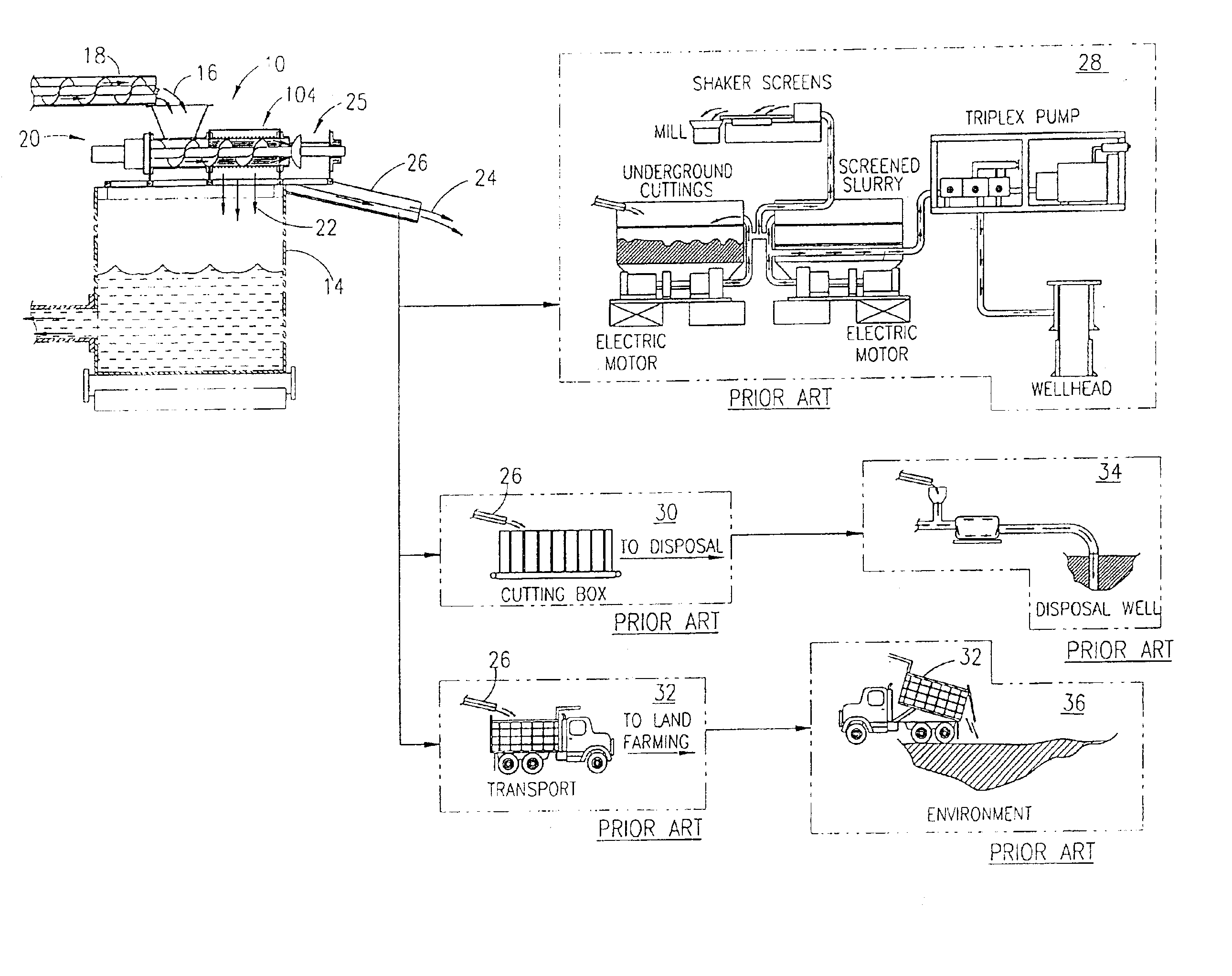
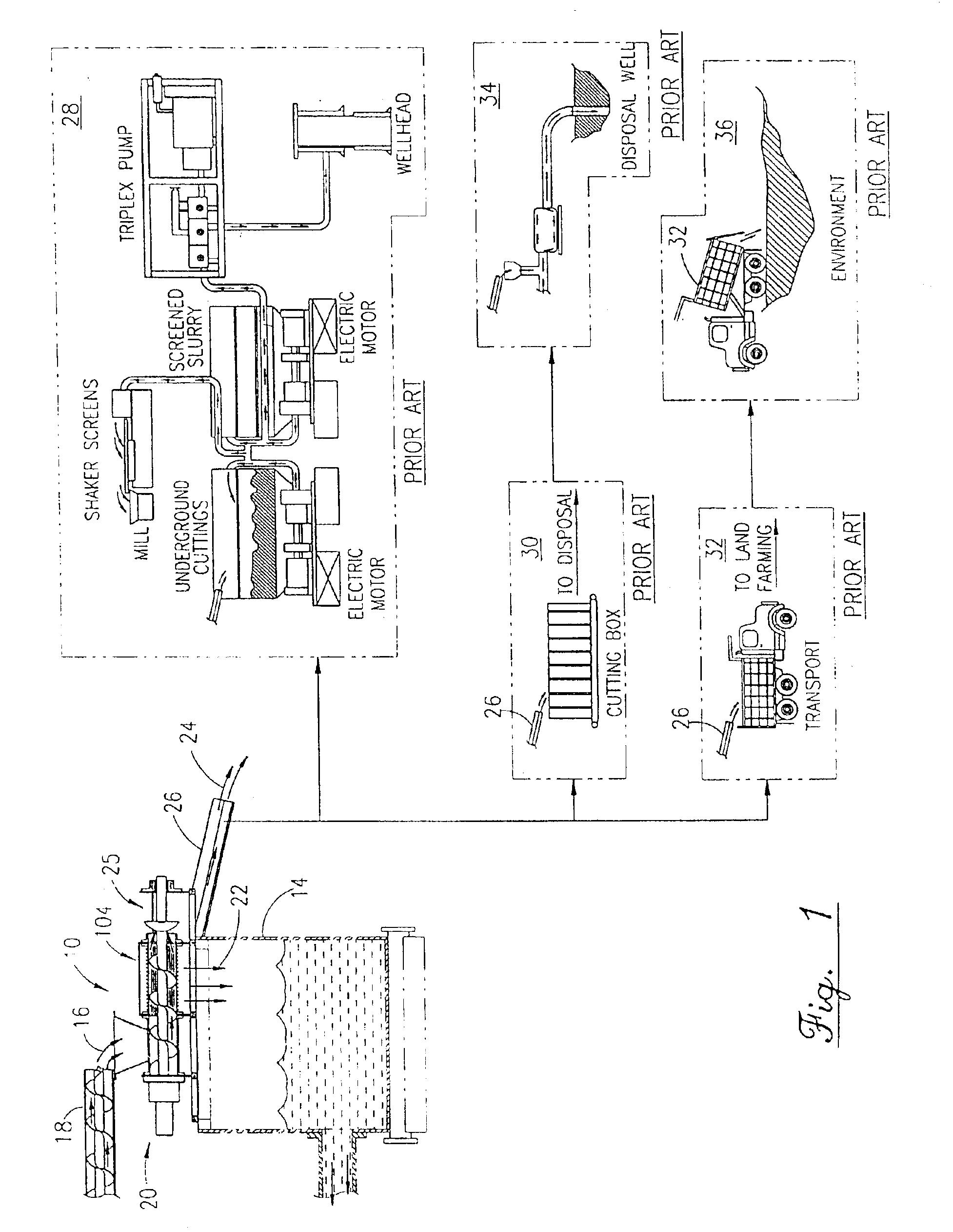
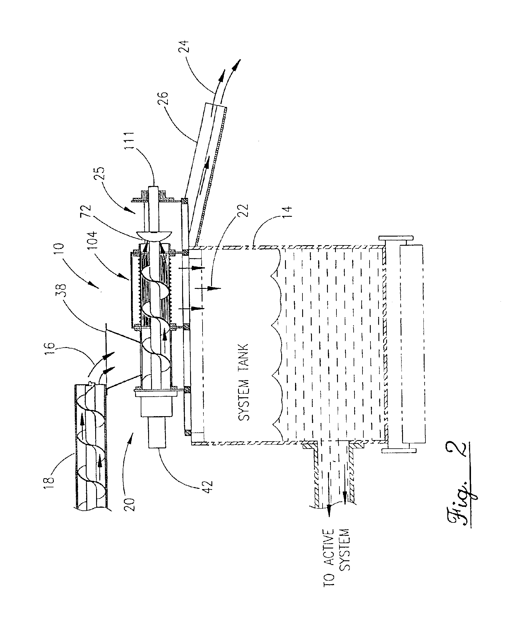
[0036]Referring first to FIG. 1 where the major components of the defluidization recovery system 10 starts with drill cuttings and drilling fluids in a slurry 16 collected from any source as overflow or underflow, usually from the rig's shaker screens (not shown). The slurry 16 is transported via a conveyor 18 to the screw press 20, shown here in cross section and better seen in FIG. 2, mounted on top of a fluid recovery tank 14, illustrating the flow path of the slurry 16 being defluidized. It is conceived that a screw press 20 or other compaction type presses depicted herein, having particular characteristics, could be mounted on or near a drilling fluids system tank 14 in which case drilling fluids contained in the overflow and underflow slurry 16 could be separated from the drill cuttings processing system prior to discharge into the environment. The slurry 16, in most cases, contains valuable drilling additives including synthetics and / or surfactants that after having passed th...


PUM


Abstract

A drill cuttings slurry process system is disclosed for defluidizing earth drill cuttings, thereby extracting valuable drilling additives and returning them to the drilling system while producing a dense, drier material which may be discharged directly in the environment at or near the well being drilled or chemically treated for distillation and / or better dissolution into the environment, thereby reducing, cost in transportation and environmental treatment chemicals thus reducing environmental contamination. The system comprising a cuttings press having solids / fluids separation a dryer and / or a retort for flashing off any residual petroleum residue and moisture, a fines grinder and a chemical injection system. The retort including an analyzer system for weighing and determining rate of throughput and analyzing the cuttings for residual petroleum residue content prior to discharge to environment or further refinement prior to reinjection into the well or transport to environmental depository sites.

Description

[0001]This is a continuation of application Ser. No. 09 / 906,944, filed on Jul. 16, 2001 now U.S. Pat. No. 6,553,901, which is a continuation-in-part of application Ser. No. 09 / 454,081, filed on Dec. 3, 1999, now U.S. Pat. No. 6,279,471, which is a continuation-in-part of application Ser. No. 08 / 713,604 filed on Sep. 13, 1996, now U.S. Pat. No. 5,996,484.BACKGROUND OF THE INVENTION[0002]1. Field of the Invention[0003]The field of the present invention relates generally to the recovery of drilling fluids from oil and gas drilling production operations, more particularly, a method and system utilizing various types of presses for the recovery of such drilling fluid through compaction and defluidization of entrained solids in a cuttings slurry prior to such cuttings being injected into a well casing or in conjunction with other environmental distribution and / or disposal operations. The system further entails an extensive drying and particle sizing process and the treatment of such cutti...

Claims


Application Information

Patent Timeline
Patent Type & Authority Patents(United States)
IPC IPC(8): B30B9/12B30B9/18E21B21/00E21B21/06
CPCB30B9/12B30B9/26E21B21/066B30B9/18
Inventor REDDOCH, JEFFREY
Owner BAKER HUGHES INC
Why Eureka
Try Eureka