Medical electrical lead connector assembly

Active Publication Date: 2007-07-10
MEDTRONIC INC
View PDF15 Cites 94 Cited by
  • Summary
  • Abstract
  • Description
  • Claims
  • Application Information

AI Technical Summary

Benefits of technology

[0003]The present invention is directed to a connector for a medical electrical lead in which a single connector delivers three or more conductors to an implantable medical device (IMD). The

Problems solved by technology

Because an additional connector port is necessary for each connector pin, the increased number of pins can result in a

Method used


Image

  • Medical electrical lead connector assembly
  • Medical electrical lead connector assembly
  • Medical electrical lead connector assembly

Examples


Embodiment Construction

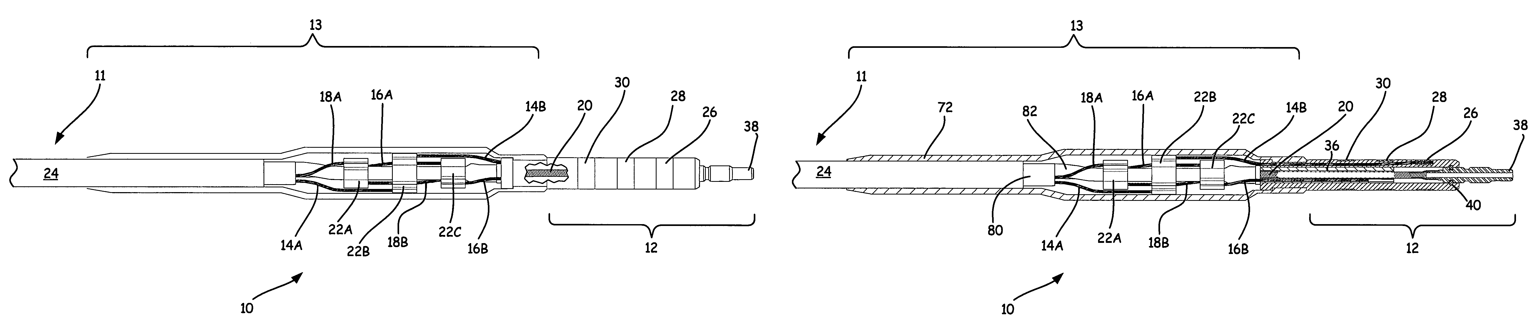
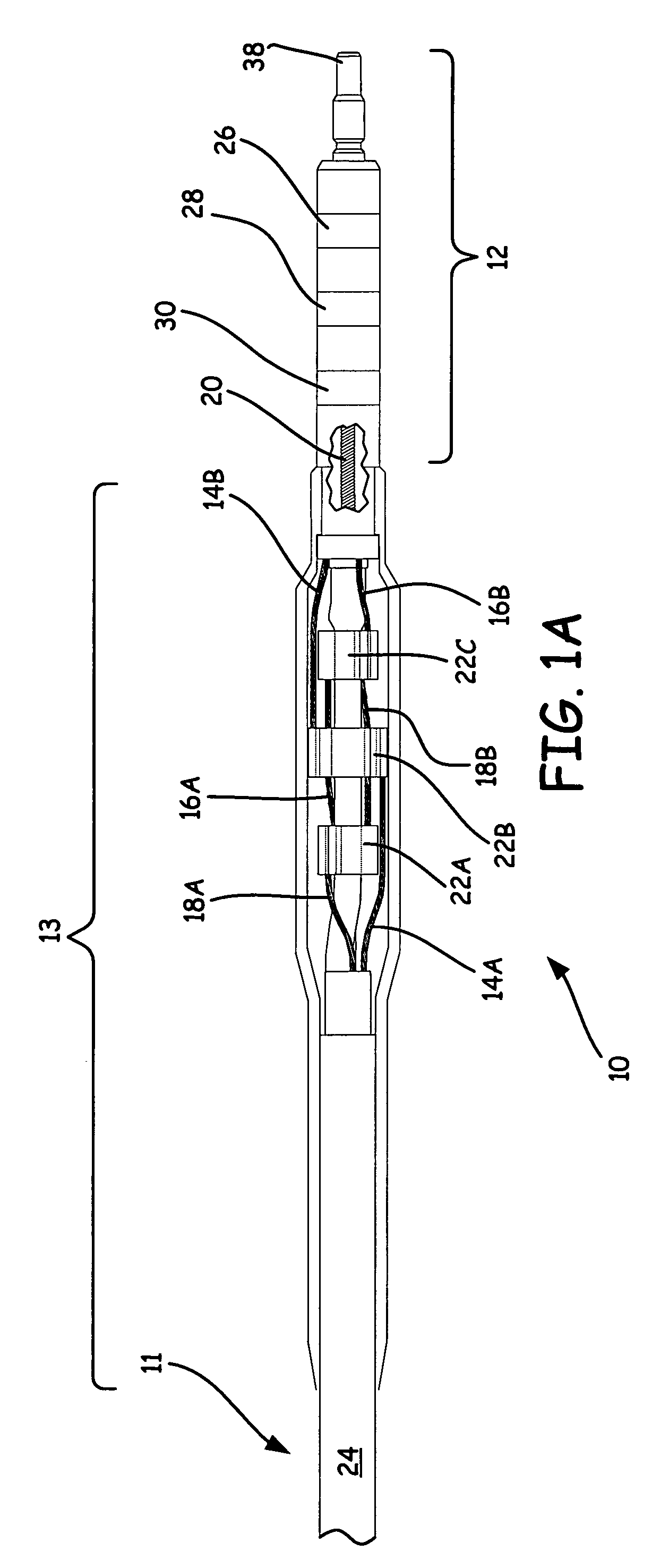
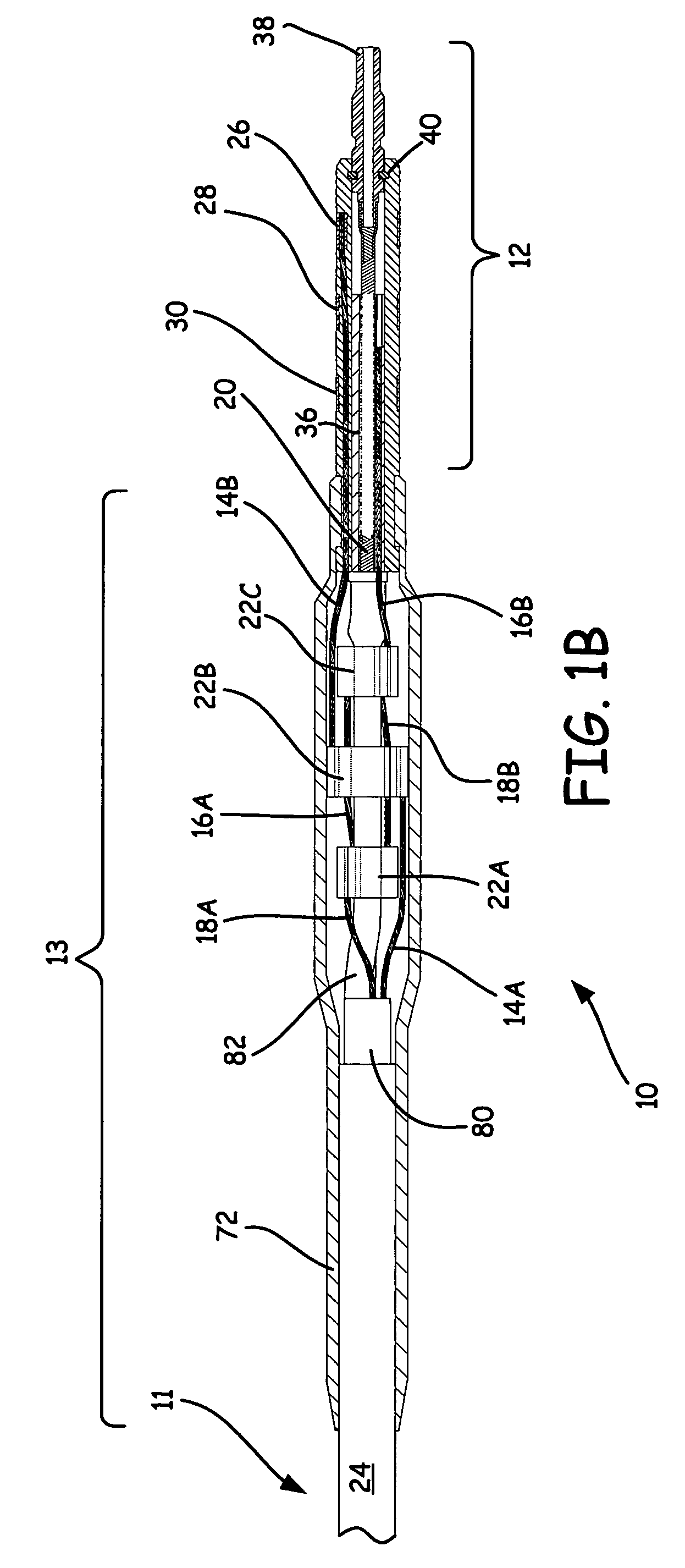
[0015]FIGS. 1A and 1B show a partially cut-away views of lead connector 10, which is used to connect multi-conductor lead 11 with an implantable medical device (IMD), such as a cardiac pacing pulse generator or implantable cardioverter defibrillator, through a single connector. Lead connector 10 is positioned at a proximal end of lead 11, and is comprised of connector assembly 12 and transition assembly 13. In the embodiment shown, lead 11 comprises a quadripolar construction in which three wire conductors (conductors 14A, 16A, and 18A) and one coil conductor (conductor 20) are delivered to or near the distal end of lead 11. Transition assembly 13 includes connector blocks 22A, 22B and 22C, which are used to coordinate the interconnection of the conductors from lead 11 to connector assembly 12.

[0016]In the embodiment described, three wire conductors are used, however it is contemplated that the lead connector of the present invention can be adapted for leads having two, four or more...


PUM


Abstract

A connector for a medical electrical lead includes a single connector, which delivers three or more conductors to an implantable medical device (IMD). The connector includes integrated multiple electrode rings and conductors, and has a modular system of connector and spacer blocks for routing the conductors to a lead body.

Description

BACKGROUND OF THE INVENTION[0001]The present invention relates generally to implantable medical device (IMD) leads for delivering active electrodes to various places in a human body, such as the heart. In particular, the present invention relates to connectors for connecting a lead with an IMD.[0002]Advances in technology have led to IMDs having increased capabilities for performing therapeutic, diagnostic and other functions. Such advances can require the use of leads carrying additional electrodes, which require additional conductors that run from the IMD to a distal end of the lead. Recently, high voltage (HV), quadripolar leads having four conductors have been introduced for tachyarrythmia management and other applications. These leads include an industry standard IS-1 connector pin for connecting the IMD with a typical coil conductor and a sensing electrode conductor for performing Brady-type pacing. In addition, for performing other pacing, sensing, defibrillation therapy and ...

Claims


Application Information

Patent Timeline
IPC IPC(8): H01R13/648H01R24/58
CPCA61N1/05A61N1/3752Y10S439/909
Inventor RENTAS TORRES, DOUGLAS
Owner MEDTRONIC INC
Why Eureka
Try Eureka