
High-pressure discharge lamp, high-pressure discharge lamp lighting device and automotive headlamp apparatus

a technology of high-pressure discharge lamp and lighting device, which is applied in the direction of gas-filled discharge tube, electric discharge lamp, solid cathode, etc., can solve the problems of insufficient amount of light immediately after lamp turn-on, and affecting the operation of the lamp. , to achieve the effect of rapid rise of luminous flux

Inactive Publication Date: 2007-07-10
HARISON TOSHIBA LIGHTING CORP +1
View PDF26 Cites 2 Cited by
  • Summary
  • Abstract
  • Description
  • Claims
  • Application Information

AI Technical Summary

Benefits of technology

The present invention is related to a high-pressure discharge lamp with a sealed discharge vessel and electrodes. The discharge vessel is fire resistant and transparent, allowing for the emission of visible light in a desired wavelength range. The electrodes are sealed at opposite ends of the discharge space in the hermetic vessel with facing each other at a distance of 5 mm or less. The electrodes have a relatively high temperature when the lamp is turned on, which causes a rapid rise in luminous flux. The discharge medium contains xenon gas and halides of light-emitting metals. The lamp power is kept low to prevent overheating. The electrodes can be controlled to have a desired temperature by adjusting design factors such as electrode diameter, length of the part of the electrode protruding into the discharge space, and lamp voltage. The electrodes can be configured for alternating current or direct current operation. The high-pressure discharge lamp provides a stable and efficient alternative to traditional high-pressure discharge lamps.

Problems solved by technology

However, nowadays environmental issues are becoming serious, and in the illuminating industry, it is considered highly important to reduce or even eliminate mercury in lamps, which applies a significant load to the environment.
However, when a high-pressure discharge lamp containing no mercury (conveniently, referred to as a “mercury-free lamp” hereinafter) is used as a light source of an automotive headlamp, there is a problem that the amount of light immediately after the lamp is turned on is insufficient.
However, in this case, another problem of discharge flicker arises.
Since the temperature of the electrodes is low in the stable state, the electrodes emit less thermoelectrons, and discharge flicker tends to occur.
Therefore, the electrodes have to be designed to have a further low temperature in the stable state, so that the discharge flicker becomes more noticeable.
However, a halide gas highly adsorbs electrons, and thus, tends to cause discharge extinction.
Therefore, as the concentration of the halide gas increases, the arc becomes less stable.
As can be understood from the reasons described above, the mercury-free lamp is highly likely to suffer discharge flicker, compared with the mercury-containing lamp.
In addition, such an electrode temperature that is not disadvantageous to the mercury-containing high-pressure discharge lamp may cause discharge flicker.
The discharge flicker may result in a luminance flicker, or, in an extreme case, extinction of the arc.

Method used


Image

  • High-pressure discharge lamp, high-pressure discharge lamp lighting device and automotive headlamp apparatus
  • High-pressure discharge lamp, high-pressure discharge lamp lighting device and automotive headlamp apparatus
  • High-pressure discharge lamp, high-pressure discharge lamp lighting device and automotive headlamp apparatus

Examples


example 1

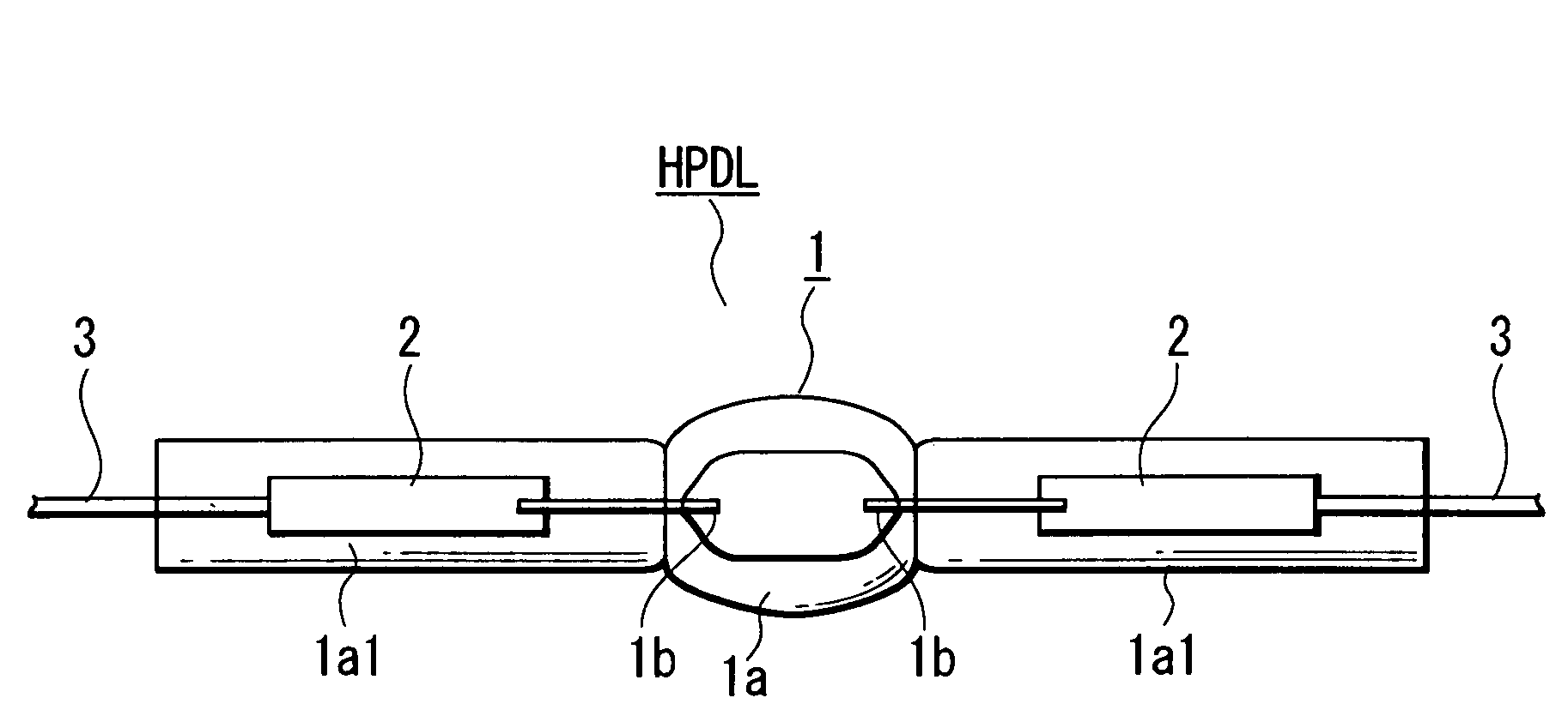
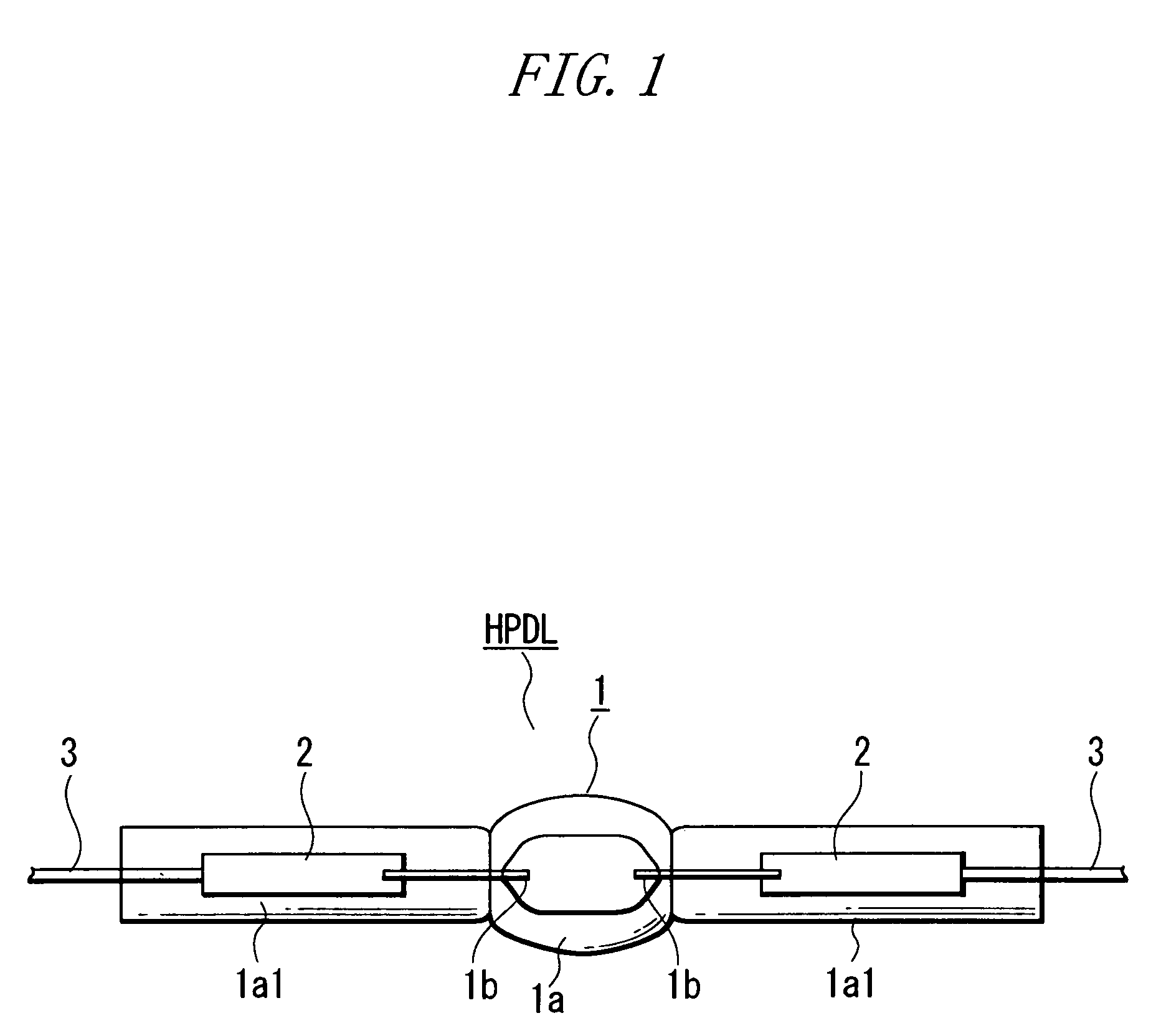
[0084]Discharge Vessel (1)

[0085]The hermetic vessel (1a) was made of quartz glass and had an outer diameter of 6 mm, an inner diameter of 2.7 mm.

[0086]The electrodes (1b) were made of tungsten, the tip ends thereof had a diameter of 0.4 mm, and the length of the parts thereof protruding into the discharge vessel was 2.3 mm.

[0087]Discharge Medium

[0088]The halides used were ScI3, NaI and ZnI2 in a relation of ScI3−NaI−ZnI2=0.2 mg.

[0089]Xenon was at 6 atmospheres.

[0090]The halogen getter used was 0.01 mg of Sc or Sb.

[0091]The lamp power in a stable state was 35 W.

[0092]The electrode temperature was 1900° C. at a point at a distance of 0.3 mm from the tip end.

[0093]The amount A of free iodine produced during 100 hours of on-time was 0.5×10⁻⁶ (mol / cc).

[0094]The value of T2 / A was 7.22×10¹².

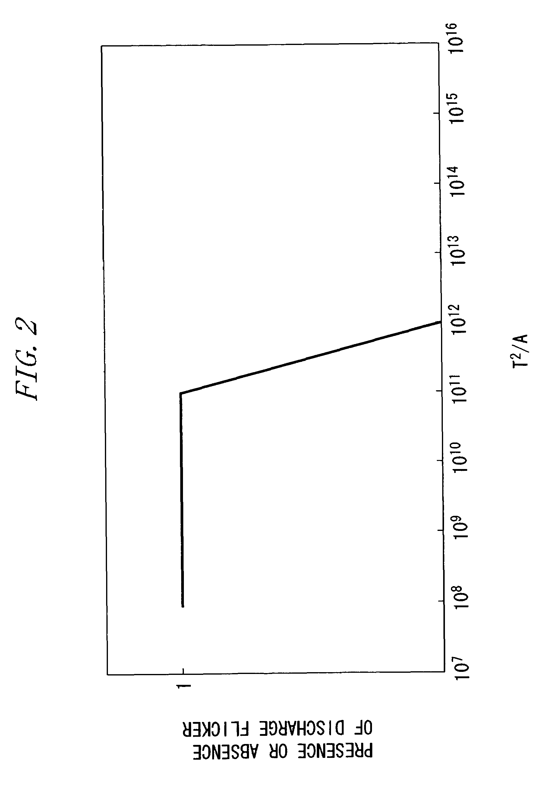
[0095]Now, with reference to FIGS. 2 to 4, relationship among the electrode temperature T (° C.), the amount A of free iodine produced (mol / cc) and the occurrence of discharge flicker will be described....

example 2

[0104]Discharge Vessel (1)

[0105]The hermetic vessel (1a) was made of quartz glass and had an inner volume of 0.025 cc, and the maximum inner diameter of the discharge space was 2.4 mm.

[0106]The electrodes (1b) were made of tungsten and had a diameter of 0.40 mm, the length of the protruding part was 1.6 mm, and the distance between the electrodes was 4.2 mm.

[0107]Discharge Medium

[0108]The halides used were ScI3, NaI and ZnI2 in a relation of ScI3−NaI−ZnI2=0.3 mg.

[0109]Xenon was at 10 atmospheres.

[0110]The lamp power immediately after the turn-on was 85 W, and the lamp power in the stable state was 35 W.

[0111]The lamp current immediately after the turn-on was 2.8 A, and the lamp current in the stable state was 0.8 A.

[0112]The electrode temperature was 1800° C. at a point at a distance of 0.3 mm from the tip end.

[0113]Now, with reference to FIG. 5, relationships between the electrode temperature in the stable state and the occurrence rate of discharge flicker and between the electrode...


PUM


Abstract

The present invention provides a high-pressure discharge lamp that uses substantially no mercury and reduces discharge flicker. The high-pressure discharge lamp is kept on with a lamp power of 50 W or lower in a stable state, and the temperature T (° C.) of the electrode at a point at a distance of 0.3 mm from the tip end to the base end in the stable state and the amount A (mol / cc) of free iodine produced when the lamp is turned off after 100 hours of on-time satisfy the formula (1):T2 / A>1011.

Description

TECHNICAL FIELD[0001]The present invention relates to a high-pressure discharge lamp substantially containing no mercury, a high-pressure discharge lamp lighting device using the same, and an automotive headlamp apparatus using the same.BACKGROUND ART[0002]High-pressure discharge lamps which have an arc tube having a pair of opposing electrodes and containing an inert gas, a halide of a light-emitting metal and mercury, that is, metal halide lamps are used widely because of their relatively high efficiency and good color rendering. Such high-pressure discharge lamps have become widely used also as automotive headlamps. Including those used as the automotive headlamps, the high-pressure discharge lamps currently in practical use essentially uses mercury (conveniently referred to as a mercury-containing lamp, hereinafter). In Japanese Patent Laid-Open No. 2-7347, there is described an exemplary specification of a high-pressure discharge lamp used as an automotive headlamp, which speci...

Claims


Application Information

Patent Timeline
Patent Type & Authority Patents(United States)
IPC IPC(8): H01J61/12H01J17/20H01J61/18H01J61/84H01J61/88
CPCH01J61/125H01J61/84
Inventor KATO, HIROYUKIKAWASHIMA, HIROMICHIUEMURA, KOZOISHIGAMI, TOSHIHIKOMATSUDA, MIKIOHIRUTA, TOSHIO
Owner HARISON TOSHIBA LIGHTING CORP
Learn More