
Small arm firing mechanism

a firing mechanism and small arm technology, applied in the direction of breech mechanism, mechanical apparatus, weapons components, etc., can solve the problems of inability to easily adjust the resistance of the trigger in such a firing mechanism, the individual elements of the firing mechanism are not returned to their starting positions after, and the risk of the firing sear of the conventional latch-type firing mechanism remaining in its position and not releasing the firing pin, etc., to achieve the effect of simple and easy adjustment of the trigger resistan

Inactive Publication Date: 2007-07-17
T SWISS ARMS TECH
View PDF17 Cites 11 Cited by
  • Summary
  • Abstract
  • Description
  • Claims
  • Application Information

AI Technical Summary

Benefits of technology

"The invention is a firing mechanism that allows for easy adjustment of the resistance of the trigger without needing to modify the construction or replace any springs. The mechanism includes an articulated lever with a catch and a latching element on the trigger. The latching groove has an oblique contact surface for the catch, and the resistance of the trigger can be adjusted by changing the contact ratios between the latching groove and the catch. The trigger also has a control surface that can be manually reset the firing mechanism in case of failure. The latching groove is preferably mounted on a detachable latch part, which makes it easy to replace or manufacture the trigger with different materials."

Problems solved by technology

Under extreme conditions such as, for example, significant soiling, gumming or icing, it may occur, however, that individual elements of the firing mechanism are not returned to their starting positions after a shot is fired.
Under the aforementioned extreme conditions, there is also a certain risk of the firing sear of conventional latch-type firing mechanisms remaining in its position and not releasing the firing pin after a shot is fired.
However, the resistance of the trigger cannot be easily adjusted in such a firing mechanism.

Method used


Image

  • Small arm firing mechanism
  • Small arm firing mechanism
  • Small arm firing mechanism

Examples


Embodiment Construction

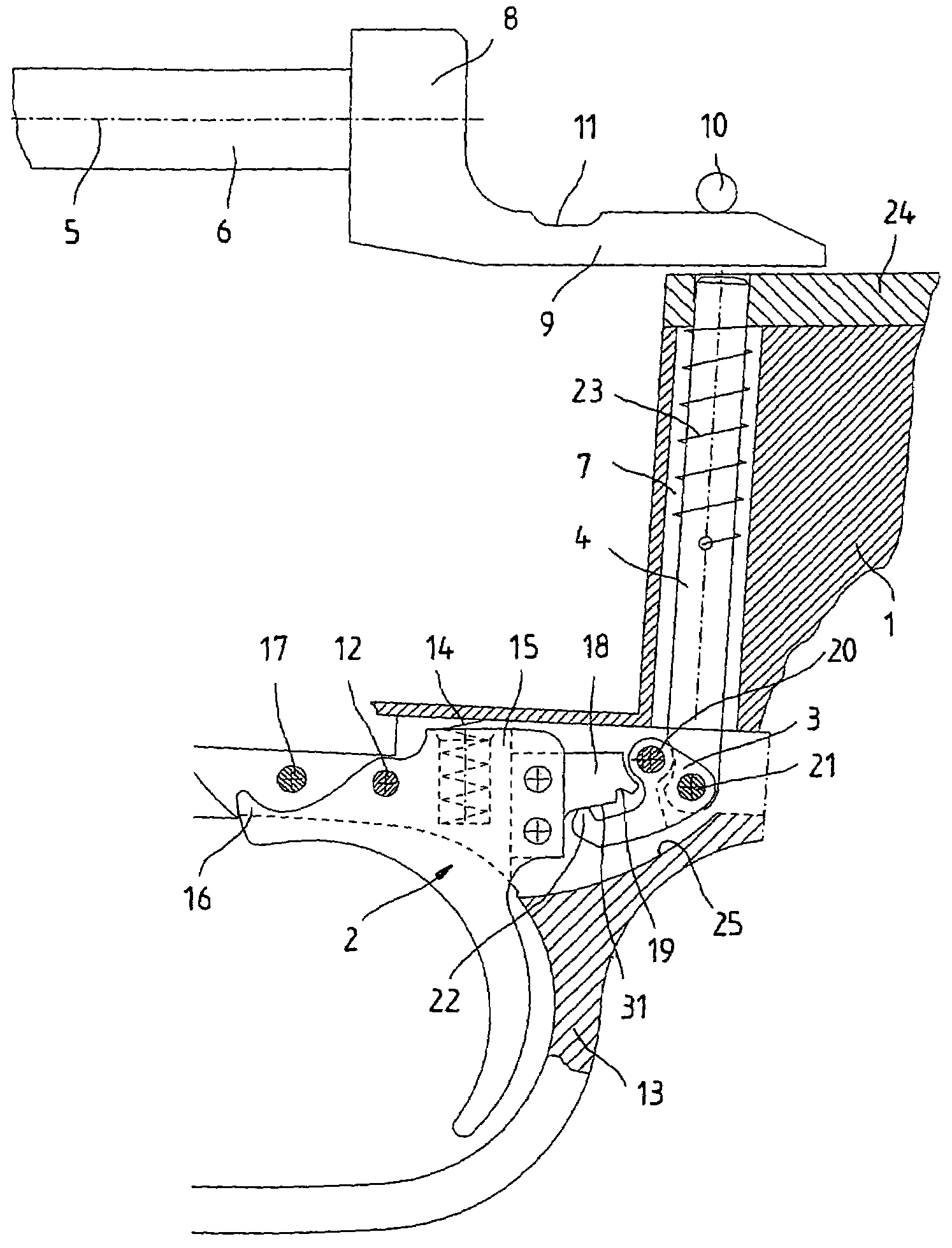
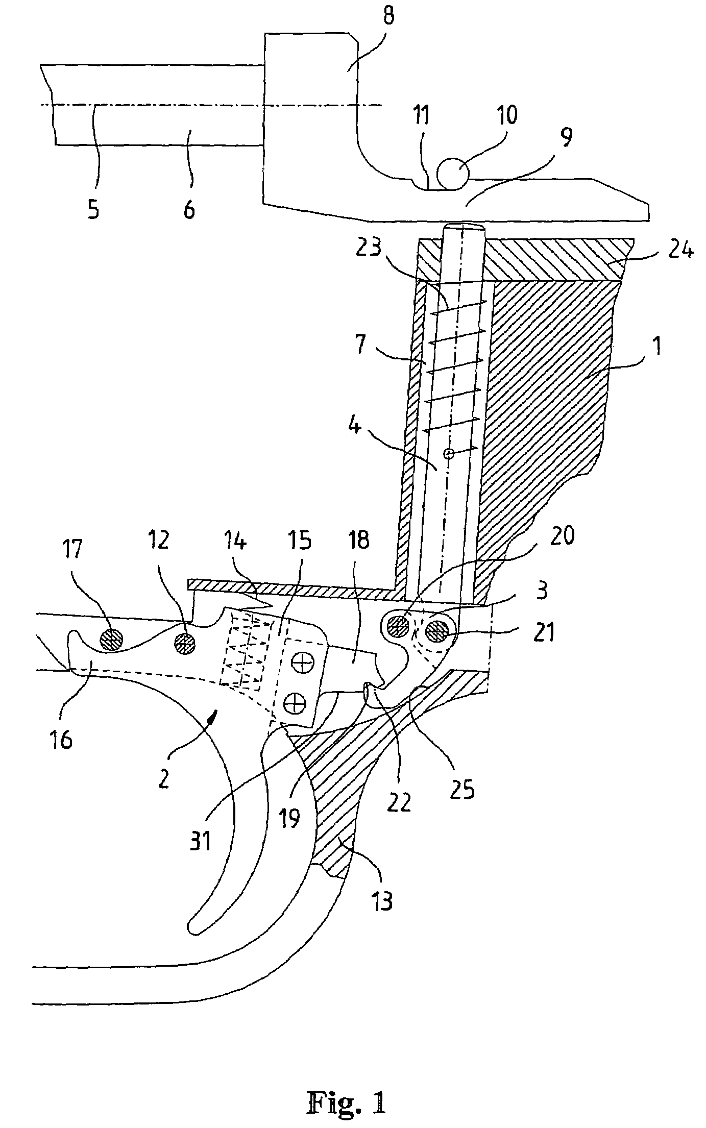
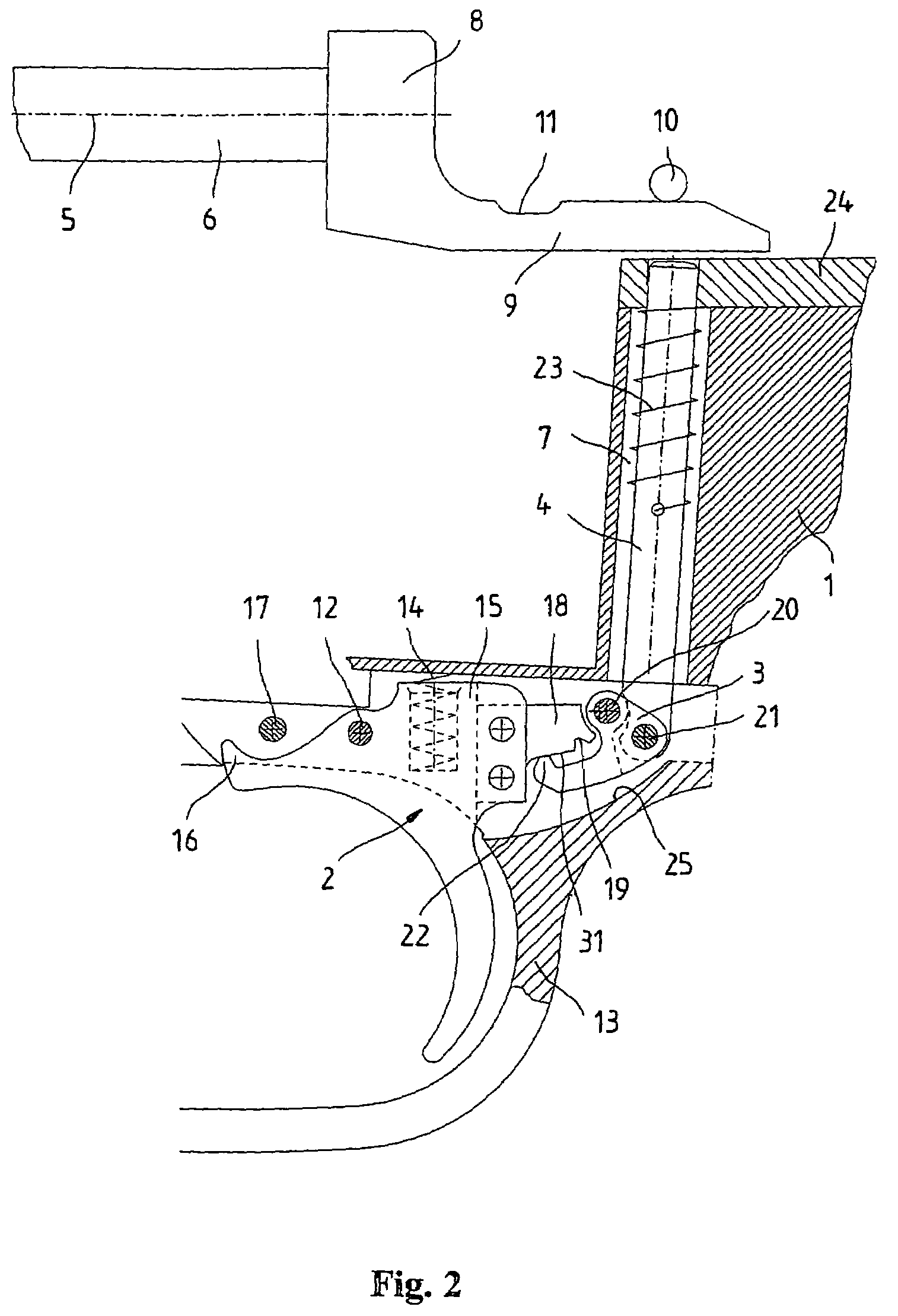
[0016]The firing mechanism that is illustrated in two different positions in FIGS. 1 and 2 comprises a pivoted trigger 2 that is arranged in a housing 1 and is connected to a trigger rod 4 that can be displaced within the housing 1 by means of an articulated lever 3. The trigger rod 4 is guided in a corresponding bore 7 of the housing 1 such that it can be displaced transverse to the longitudinal axis 5 of a firing pin 6. The firing pin 6 is only partially illustrated in the figure, and comprises a cocking piece 8 with a rearwardly projecting web 9 on its rear end. The trigger rod 4 presses this web upward against a stationary transverse pin 10. The upper side of the web 9 is provided with a depression 11 that serves for accommodating the stationary transverse pin 10 in order to retain the firing pin 6 in a cocked rear position.

[0017]The trigger 2 is pivotably mounted in the housing 1 about a trigger axis 12, and is surrounded by the trigger guard 13. A trigger spring 14 presses the...


PUM


Abstract

The invention pertains to a firing mechanism for a small arm, particularly a rifle, with a trigger (2) that can be pivoted about a trigger axis (12), with a trigger rod (4) that is displaceably arranged within a housing (1) and serves for respectively retaining and releasing a prestressed firing pin (6), and with an articulated lever (3) that is arranged within the housing (1) such that it can be pivoted about a pivot axis (20) and is connected in an articulated fashion to the trigger rod (4), with said articulated lever being connected to the trigger (2) via the trigger rod (4). The resistance of the trigger can be easily changed without requiring significant constructive modifications if the articulated lever (3) that is connected in an articulated fashion to the trigger rod (4) has an upwardly protruding catch (22) that engages into a lower latching groove (19) on the trigger (2) in a cocked position of the firing mechanism, with the latching groove (19) being provided with an oblique stopping face (33) for a front edge (34) of the catch (22).

Description

FIELD OF THE INVENTION[0001]The invention pertains to a firing mechanism for a small arm, particularly a rifle, with a trigger that can be pivoted about a trigger axis.BACKGROUND OF THE INVENTION[0002]In classic latch-type firing mechanisms, the firing lever is provided with a latch element that engages with a complementary latch element of a trigger plate in the cocked position. When a shot is fired with such a latch-type firing mechanism, the latch elements are disengaged and the trigger elements are separated from one another. This means that another spring needs to be provided in addition to the trigger spring in order to cock the firing mechanism anew. This additional spring presses the trigger lever and the firing sear back into their engaged starting position. Under extreme conditions such as, for example, significant soiling, gumming or icing, it may occur, however, that individual elements of the firing mechanism are not returned to their starting positions after a shot is ...

Claims


Application Information

Patent Timeline
Patent Type & Authority Patents(United States)
IPC IPC(8): F41A19/16F41B
CPCF41A19/16
Inventor ZEH, MEINRAD
Owner T SWISS ARMS TECH
Learn More