Vehicle drag reduction apparatus

a technology of drag reduction and vehicle, which is applied in the direction of vehicle body streamlining, monocoque construction, vehicle body structure, etc., can solve the problems of time-consuming operation of removal and storage of streamlining devices, and the box-like configuration is not aerodynamically efficient, and the aerodynamic drag resulting from the box shape accounts for a considerable percentage of the fuel consumption of large trucks and tractor-trailer combinations

Inactive Publication Date: 2007-07-17
VALA PHILIP
View PDF57 Cites 93 Cited by
  • Summary
  • Abstract
  • Description
  • Claims
  • Application Information

AI Technical Summary

Benefits of technology

[0011]Accordingly, it is a principal advantage of the present invention to provide a vehicle air drag reduction system, to be fitted to a rear substantially flat surface of a vehicle, which comprises a flexible panel having at least three, preferably straight, support rod passages, which panel is adapted to be affixed to the vehicle. The support rod passages are preferably essentially parallel, and are each adapted to receive a support rods which extends through the passage so as to provide structural support for the flexible panel.
[0012]At each end of the support rods are fittings which are adapted to be fixed to a support rod receiver. A series of support rod receivers or brackets are temporarily or permanently affixed to the rear end of the trailer; either on the substantially flat surface of the vehicle, or on a side, top or bottom surface of the trailer, operatively adjacent to the flat surface. Preferably, the receivers or brackets are located at or near the top and bottom edges of the trailer flat surface.
[0013]Accordingly, in one aspect, the present invention provides a vehicle air drag reduction system for mounting on the rearward surface of a vehicle, wherein said rearward surface of said vehicle on which said system is to be mounted, is substantially flat and rectangular, with opposed vertically disposed side edges and opposed horizontally disposed upper and lower edges;said vehicle air drag reduction system comprising:
[0014]a flexible panel to be affixed to said rearward surface, and extending, in use, essentially between said disposed side edges and essentially between said upper and lower edges, and having two exterior support rod passages, and at least one interior support rod passage positioned between said exterior support rod passages, all of which support rod passages extend from one edge of said flexible panel to an opposite edge thereof;
[0015]two exterior support rods and at least one interior support rod, each of which are positioned substantially within said exterior or interior support rod passages respectively, so as to provide structural support for the flexible panel, and each having a support rod end fitting extending out of said support rod passages at each end of said support rod passage;
[0016]a series of support rod brackets affixed to said vehicle in a substantially linear fashion on opposing edges of said vehicle, and corresponding alignment with said support rod passages, into which brackets said support rod ends are fitted;

Problems solved by technology

It is also well known that this boxlike configuration is not aerodynamically efficient and that the aerodynamic drag resulting from the box shape accounts for a considerable percentage of the fuel consumption of large trucks and tractor-trailer combinations during higher speed applications, such as on a highway.
However, in the prior art devices, removal and storage of the streamlining devices is typically a time-consuming operation.
Also, removal of the devices also requires storage space on the truck if the operator wishes to keep possession of the device in the situation where a trailer is left at a location.
Further, permanent mounting of the device on the truck or trailer doors undesirably exposes the device to adverse weather and other conditions during times of non-use of the device.
The exposed device is also subject to other potential damage, such as acts of vandalism, or the like.
It will be easily appreciated that such exposure and potential damage shortens the life of the device.
While this device provides some improvement over prior art devices, it requires a series of belts and gaskets to seal to the trailer, and can be difficult to use when access to the interior of the truck or trailer is desired.
However, the entire device is not easily removed (or re-installed) from the trailer, and is not readily portable once removed.
Also, the entire device is not easily stored due to the bulk of the belt assembly, and because of the collection of crossing support battens and rods.
As a result, few of these designs have been adopted to any significant extent.

Method used


Image

  • Vehicle drag reduction apparatus
  • Vehicle drag reduction apparatus
  • Vehicle drag reduction apparatus

Examples


Embodiment Construction

[0035]The novel features which are believed to be characteristic of the present invention, as to its structure, organization, use and method of operation, together with further objectives and advantages thereof, will be better understood from the following drawings in which a presently preferred embodiment of the invention will now be illustrated by way of example only. In the drawings, like reference numerals depict like elements.

[0036]It is expressly understood, however, that the drawings are for the purpose of illustration and description only and are not intended as a definition of the limits of the invention.

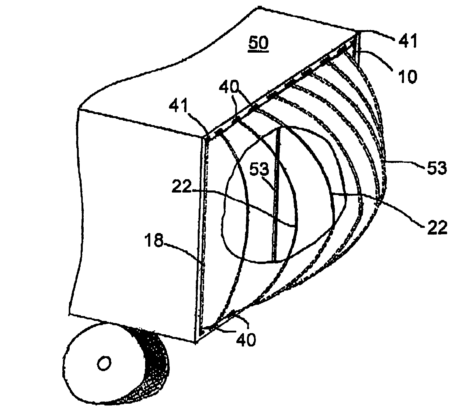
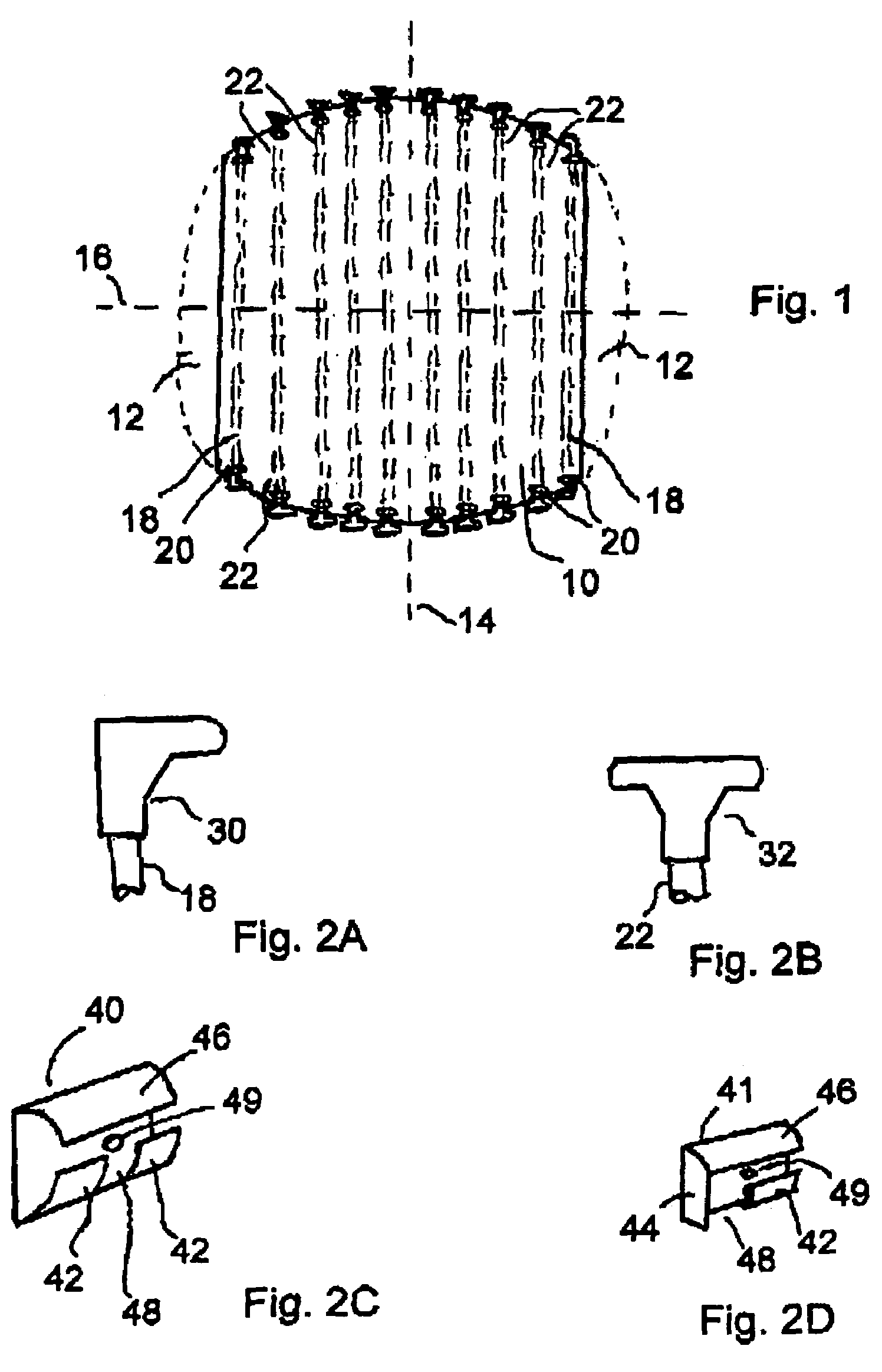
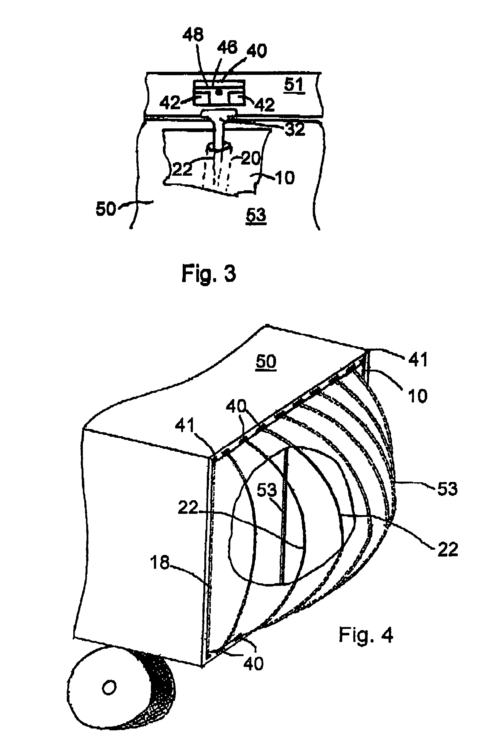
[0037]It is to be noted however, that while a truck trailer assembly is shown in the drawings, the vehicle drag reduction system and apparatus of the present application may be mounted on the rearward surface of any suitable vehicle which may typically be one of the following, namely: trucks, trailers, buses, motorized recreational vehicles, recreational trailers, cargo tra...


PUM


Abstract

A vehicle air drag reduction system is provided for mounting on the rearward facing surface of a vehicle, and in particular a truck trailer, that provides improved efficiency. The system comprises a flexible panel that will assume a cone-shape at the rearward end of the trailer, and which is held in place by a plurality of support rods fitted within the flexible panel, and which attach to brackets mounted on said trailer. An inexpensive and simple air drag reduction system is provided which is easily attached or removed from a vehicle is provided.

Description

FIELD OF THE INVENTION[0001]This invention relates to a device, and system, for air drag reduction on vehicles. In particular, this invention relates to such a device which may be easily mounted and dismounted to and from a vehicle. Moreover, the vehicle drag reduction apparatus and system of the present invention is such that when mounted to the rear surface of a vehicle, it may be easily collapsed from its working configuration to a folded, storage configuration, so as to allow easy access to the rear surface of the vehicle.BACKGROUND OF THE INVENTION[0002]It is well known that the box-like shape of truck storage areas, and the trailer sections of a tractor-trailer combination, results from the need or desire to optimize cargo space. It is also well known that this boxlike configuration is not aerodynamically efficient and that the aerodynamic drag resulting from the box shape accounts for a considerable percentage of the fuel consumption of large trucks and tractor-trailer combin...

Claims


Application Information

Patent Timeline
Patent Type & Authority Patents(United States)
IPC IPC(8): B62D35/00
CPCB62D35/004F15D1/10
Inventor VALA, PHILIP
Owner VALA PHILIP
Why Eureka
Try Eureka