Sheath device with dressing for prevention of pneumothorax.

a technology of pneumothorax and dressing, which is applied in the field of dressings with dressings for preventing pneumothorax, can solve the problems of respiratory failure, lung infection, respiratory failure, etc., and achieve the effect of facilitating the healing of the chest incision

Inactive Publication Date: 2007-07-17
PUROW BENJAMIN
View PDF15 Cites 65 Cited by
  • Summary
  • Abstract
  • Description
  • Claims
  • Application Information

AI Technical Summary

Benefits of technology

[0006]In accordance with the present invention, a combination sheath and dressing device is provided for use in assisting in the removal of chest tubes from patients and the dressing of the tube incision in the chest. The device allows a chest tube to be removed without allowing air into in the chest cavity during the removal process, and facilitates the healing of the chest incision after the tube is removed. The device preferably includes an air-

Problems solved by technology

Pneumothorax, or the passage of air into the pleural cavity, is undesirable because it allows the chest cavity to lose pressurization and decreases the expansion capability of the lungs.
Further complications associated with pneumothorax include respiratory failure and lung infection.
In many cases, however, the dressing placed over the opening is not completely air impermeable, or the attendant may have difficulty holding the opening closed while suturing the opening.
While

Method used


Image

  • Sheath device with dressing for prevention of pneumothorax.
  • Sheath device with dressing for prevention of pneumothorax.
  • Sheath device with dressing for prevention of pneumothorax.

Examples


first embodiment

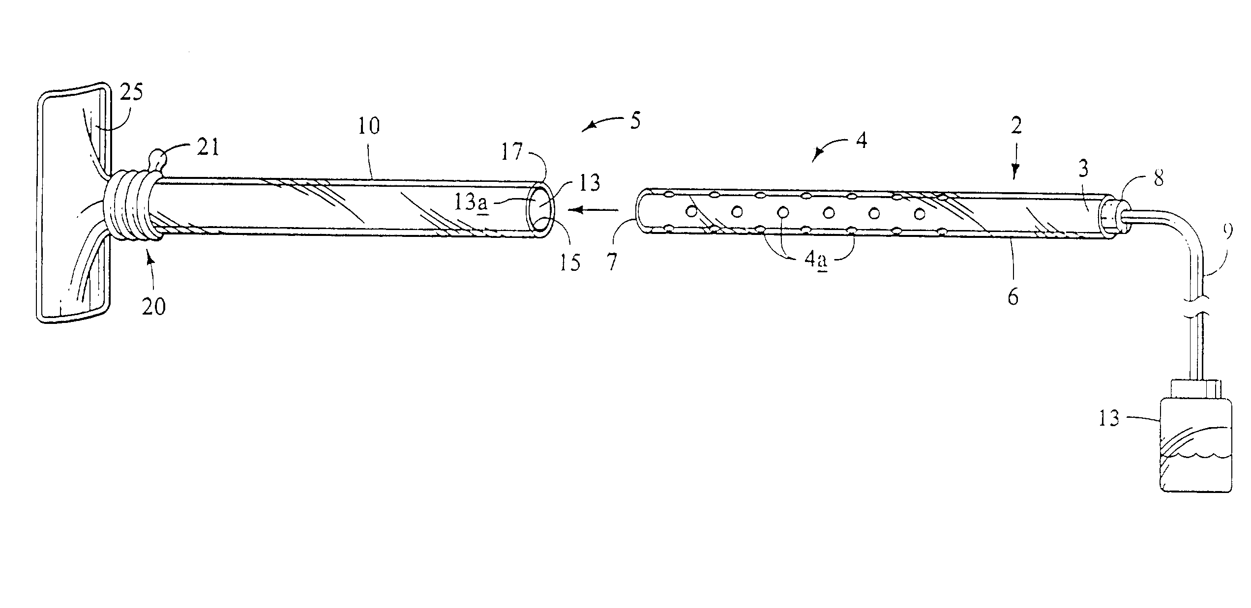
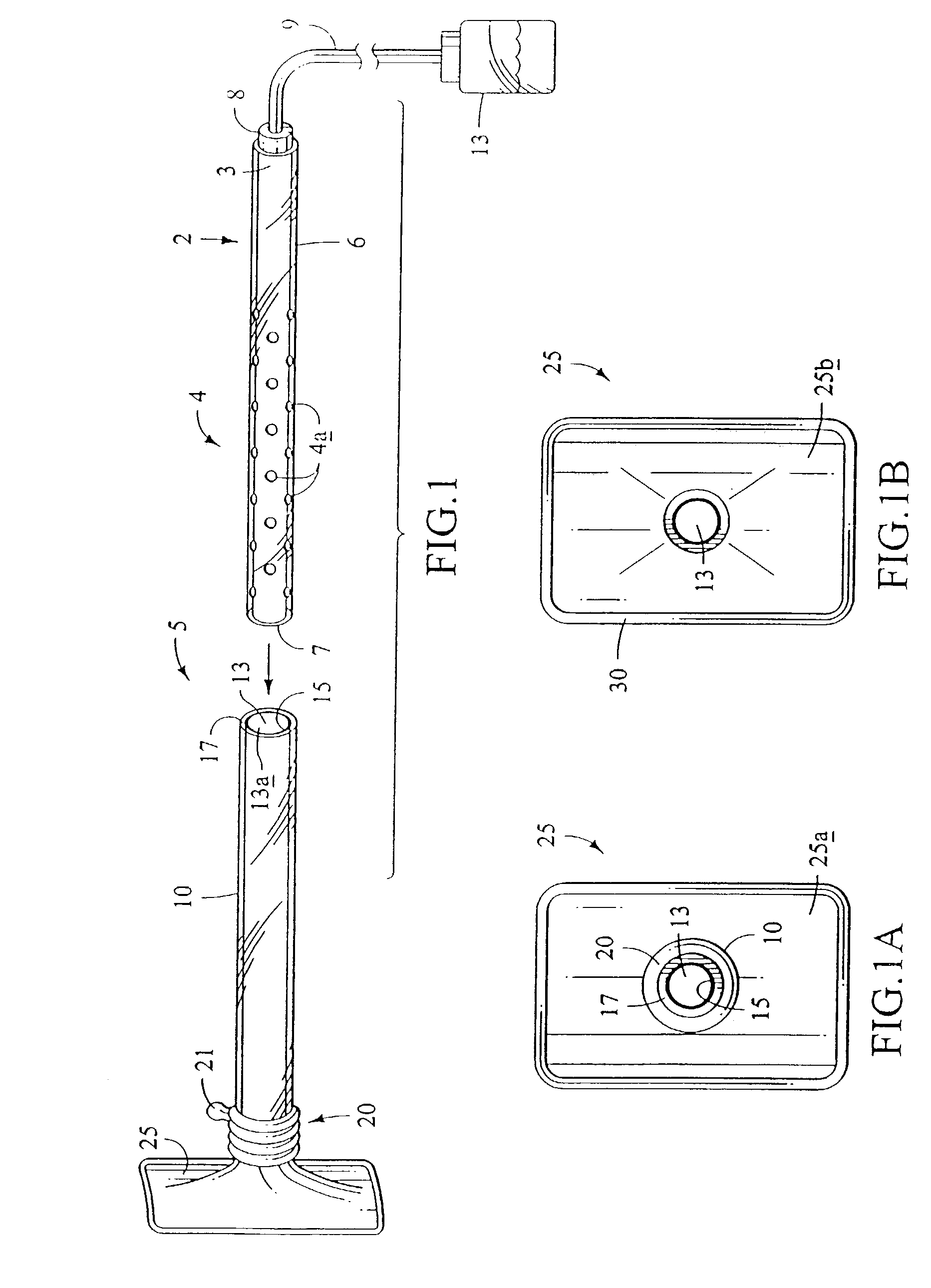
[0028]The joint 20 is preferably a flexible and air-impermeable boot that joins the body 10 with the base 25. By “flexible” it is meant that the material forming the joint 20 can be bent with minimal effort. The joint includes ridged annular raised portions 21 along its walls to provide a corrugated structure that allows the joints to be bent to approximately 90° without closing off its internal throughgoing airspace. The joint 20 is attached at one end with the base 25 and attached at the opposing end with the body 10. Preferably, the joint 20 is constructed of a latex material having a wall thickness sufficient to support its annular corrugated structure. Other, non-corrugated configurations may of course be utilized to lend flexibility to the structure of the joint 20. In a first embodiment, the joint 20 between body 10 and the chest tube 2 may be manually sealable, as described below.

[0029]As shown in FIG. 1a, the base 25 includes a front side 25a that is sealed to the joint 20....

embodiment 300

[0038]In another embodiment 300, the joint 320 may be automatically self-sealable, as depicted in FIG. 9. As shown in the Figure, the interior of the joint 320 includes self-sealing adhesive strips having portions 340a and 340b. Preferably, the adhesive portions of the strips 340a and 340b generally face each other. After the chest tube is removed past the joint 320 into the body 310, the adhesive strips 340a may be pinched manually onto adhesive strip 340b within the joint 320 from the outside of the joint 320, creating an air-impermeable seal in the joint 320. The body 310 and a portion of the joint 320 may then be separated from the sealed dressing portion as described above. As in the above-described embodiment, the automatically sealable embodiment provides a mechanism with which a chest tube is removed in an airtight environment, thereby significantly reducing the risk of pneumothorax.

[0039]In another embodiment of the invention, to further speed chest tube removal while preve...


PUM


Abstract

A sheath device comprises a substantially rigid elongated body adapted to receive a chest tube. The body includes a first end and a second end, flexible seal at the first end, and an air-impermeable flexible joint at the second end. A base having a first side and a second side is provided at the joint, wherein the first side is connected with the flexible joint and the second side includes an adhesive for securing the base to a patient's chest. A method of preventing pneumothorax in a patient having a chest tube removed comprises attaching the sheath device to the patient's chest at the time of the chest tube placement, later withdrawing the chest tube into the airtight chamber of the sheath, and sealing the sheath device. Removing the base and flexible joint of the sheath device from the body of the sheath device leaves an air-impermeable dressing on the patient's chest.

Description

[0001]This application is a continuation of application Ser. No. 09 / 689,545, filed Oct. 12, 2000, now U.S. Pat. No. 6,569,121.BACKGROUND OF THE INVENTION[0002]In a healthy person, the pleural chest cavity is generally an airtight, airless environment. During normal respiration, the contraction of the diaphragm increases the volume of the cavity, which in turn decreases the pressure therein and causes the lungs to expand. Normally, air cannot enter or escape the pleural cavity.[0003]Patients who have fluid or air in this cavity may be treated by inserting a chest tube into the pleural cavity to drain this fluid or air. The chest tube typically comprises a plastic tube having drainage holes at its tip and in a section of its sidewall and is inserted through an incision in the wall of the patient's chest. Ordinarily, the tube is connected to a collection container for holding the drained fluids. When the cavity of a given patient has been drained and the underlying cause of the fluid b...

Claims


Application Information

Patent Timeline
IPC IPC(8): A61M5/32A61M27/00
CPCA61M27/00A61M2210/1039
Inventor PUROW, BENJAMIN WARRENCHU, MICHAEL P.
Owner PUROW BENJAMIN
Why Eureka
Try Eureka