Al technical title is built by PatSnap Al team. It summarizes the technical point description of the patent document.
a technology of alternator and tester, which is applied in the direction of measurement using ac-dc conversion, instruments, nuclear elements, etc., can solve the problems of cumbersome test, difficult to handle, and perceived battery failur
Inactive Publication Date: 2007-07-17
MIDTRONICS
View PDF430 Cites 86 Cited by
Summary
Abstract
Description
Claims
Application Information
AI Technical Summary
This helps you quickly interpret patents by identifying the three key elements:
Problems solved by technology
Method used
Benefits of technology
Problems solved by technology
With the advent of accurate battery testing, it has become apparent that in some instances the battery in the vehicle may be good, and a problem related to the battery charging system is the cause of the perceived battery failure.
Such a test is cumbersome as the equipment is large and difficult to handle.
Further, it is difficult, particularly with compact engines, to reach the alternator output cable.
Further, in some cases, the amp clamp may not fit around the output cable.
It is also very easy to place the amp clamp around the wrong cable causing a false test.
Method used
Image
Click on the blue label to locate the original text in one second.
Reading with bidirectional positioning of images and text.
Examples
Embodiment Construction
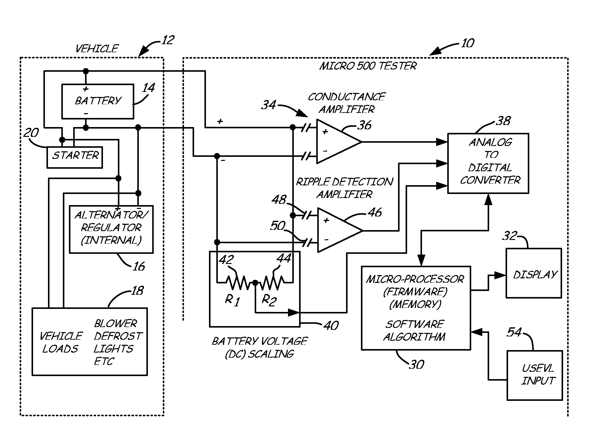
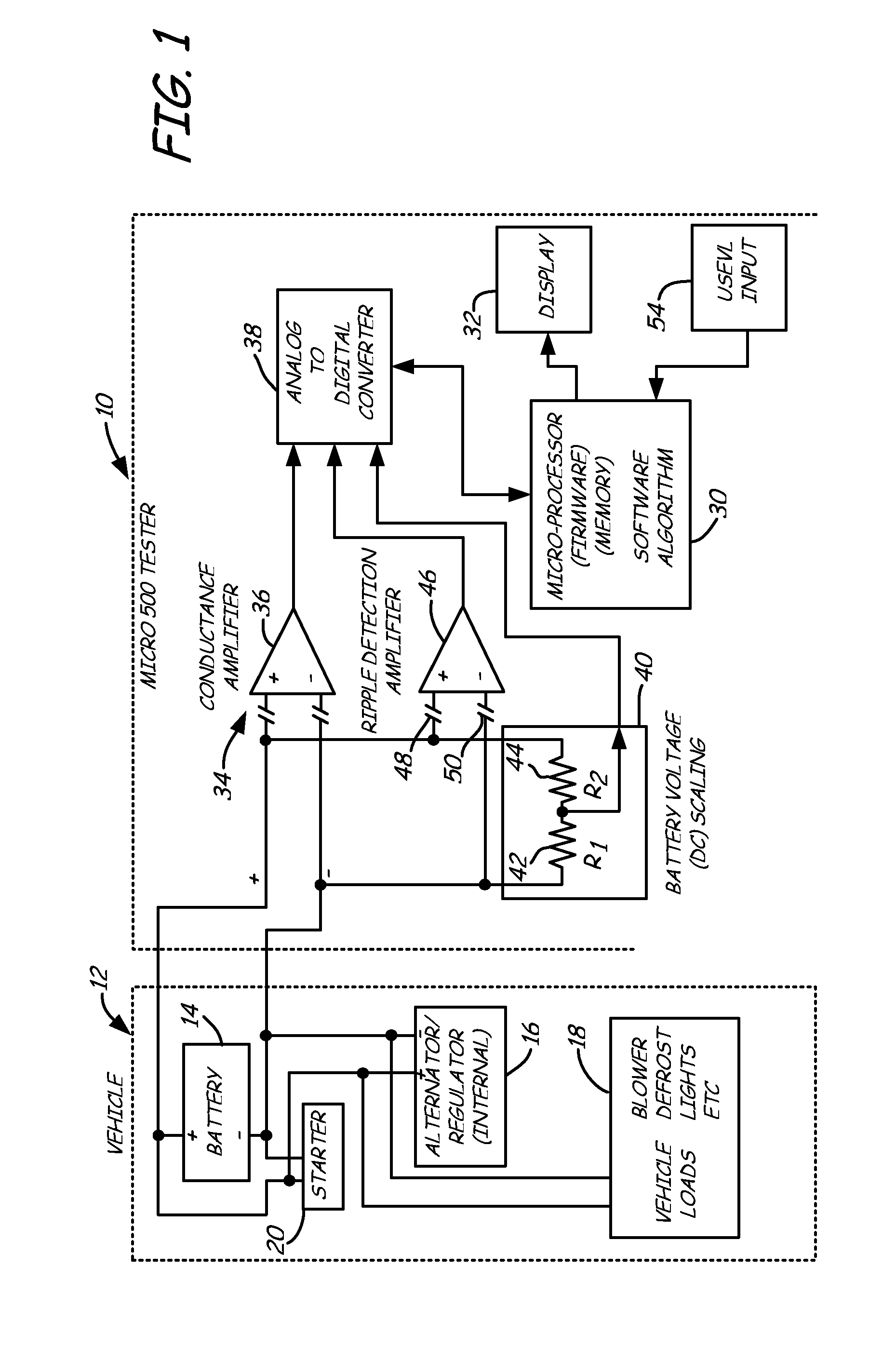
[0020]FIG. 1 is a simplified block diagram of a battery charging system tester 10 in accordance with one embodiment of the present invention coupled to a vehicle 12. Vehicle 12 includes a battery 14 having positive and negative terminals, an alternator with internal regulator 16, various vehicle loads 18, and a starter motor 20. In operation, battery 14 provides power to starter 20 and vehicle loads 18 when the engine in vehicle 12 is not running. When the engine in vehicle 12 is running, alternator 16 is used to power vehicle loads 18 and provide a charging current to battery 14 to maintain the charge of battery 14.
[0021]Charging system tester 10 includes a microprocessor 30 which controls operation of tester 10 and provides instructions and test result information to an operator through, for example, a display 32. Tester 10 includes a battery testing section 34 which is illustrated generally as conductance amplifier 36. Section 34 operates in accordance with, for example, the cond...
PUM
Abstract
An alternator tester is provided for testing an alternator of a vehicle while the alternator is coupled to the vehicle. A sensor is configured to couple to the vehicle and sense a signal related to operation of the alternator. A memory contains data related to operator instructions for performing an alternator tester of a function of vehicle type. A processor configured to provide an output indication of alternator condition based upon the sensed signal. An extra load or connection can be provided for coupling to the electrical system.
Description
BACKGROUND OF THE INVENTION[0001]The present application is based on and claims the benefit of U.S. provisional patent application Ser. No. 60 / 477,082, filed Jun. 9, 2003, the present application is a Continuation-In-Part of and claims priority of U.S. patent application Ser. No. 10 / 098,741, filed Mar. 14, 2002, now U.S. Pat. No. 6,885,195 which is a Continuation-In-Part of U.S. patent application Ser. No. 09 / 575,629, filed May 22, 2000, now U.S. Pat. No. 6,445,158, which is a Continuation-In-Part of Ser. No. 09 / 293,020, filed Apr. 16, 1999, now U.S. Pat. No. 6,351,102; which is a Continuation-In-Part of Ser. No. 09 / 426,302, filed Oct. 25, 1999, now U.S. Pat. No. 6,091,245; which is a Divisional of Ser. No. 08 / 681,730, filed Jul. 29, 1996, now U.S. Pat. No. 6,051,976, the content of which is hereby incorporated by reference in its entirety.[0002]The present invention relates to devices for testing an automotive vehicle. More specifically, the present invention relates to a battery c...
Claims
Application Information
Patent Timeline
Application Date:The date an application was filed.
Publication Date:The date a patent or application was officially published.
First Publication Date:The earliest publication date of a patent with the same application number.
Issue Date:Publication date of the patent grant document.
PCT Entry Date:The Entry date of PCT National Phase.
Estimated Expiry Date:The statutory expiry date of a patent right according to the Patent Law, and it is the longest term of protection that the patent right can achieve without the termination of the patent right due to other reasons(Term extension factor has been taken into account ).
Invalid Date:Actual expiry date is based on effective date or publication date of legal transaction data of invalid patent.