Mattress assembly

a mattress and assembly technology, applied in the field of mattresses, can solve the problems of sprains and breaks, rise to a multiplicity of lawsuits against hospitals and long-term care facilities, and more serious injuries, including death, can also occur, and achieve the effects of reducing the risk of injury, avoiding injury, and avoiding injury

Inactive Publication Date: 2007-07-24
DILIBERTO JR SAMUEL L
View PDF18 Cites 27 Cited by
  • Summary
  • Abstract
  • Description
  • Claims
  • Application Information

AI Technical Summary

Benefits of technology

[0027]It is therefore an object of this invention to eliminate or greatly reduce the risk of entrapments and injuries sustained therefrom. Preferably, the invention, through proper implementation and monitoring, will eliminate the need for bed safety rail entirely in some cases, or substantially limit the need for their use in others.
[0036]It is a further object of this invention to provide a mattress assembly that is easily sanitized, washed and cleaned.

Problems solved by technology

Although the use of these safety rails provides some degree of protection against the risk of the patient falling off the bed, these safety rails present their own safety concerns.
Bruising, sprains and breaks would result from minor events.
More serious injuries, including death, can also occur in cases of prolonged events involving choking or suffocating entrapments.
These safety concerns have given rise to a multiplicity of lawsuits against hospitals and long-term care facilities.
As is apparent, this alternative arrangement is not optimal and presents its own set of problems.
“However, in solving one problem, this type of solution could introduce an additional difficulty: the bed occupant becoming stuck in the gap described by the interface of the inflatable side support and the mattress.
However, the low sides of this safety fence are designed solely to prevent the occupant from falling out of the bed and not from sustaining injury as a result of contact with nearby solid structure during the course of a fit or other such uncontrolled body movement.
The integral type padding arrangements are inconvenient and not adaptable to a wide variety of currently manufactured beds while the latter variety provide at best inadequate padding and typically allow the patient a gap or space between the bed mattress and the padded rail into which an arm, elbow or ankle may easily slip providing an opportunity for patient injury.
The disadvantages of these structures has been described above.
While this device addresses some of the problems in the prior art, it has not proven completely satisfactory.
This may be inconvenient or cause additional cost to the user.
Additionally, should a mattress be slightly deformed or manufactured imperfectly, a risk of a gap between the mattress and the wall of the device is created, defeating the very purpose of using the device to prevent gaps and decrease the possibility of entrapment.
Another disadvantage is that some polymeric materials used to manufacture inflatable devices support the growth of bacteria or produce latex-type allergic reactions in some patients.

Method used


Image

  • Mattress assembly
  • Mattress assembly
  • Mattress assembly

Examples


Embodiment Construction

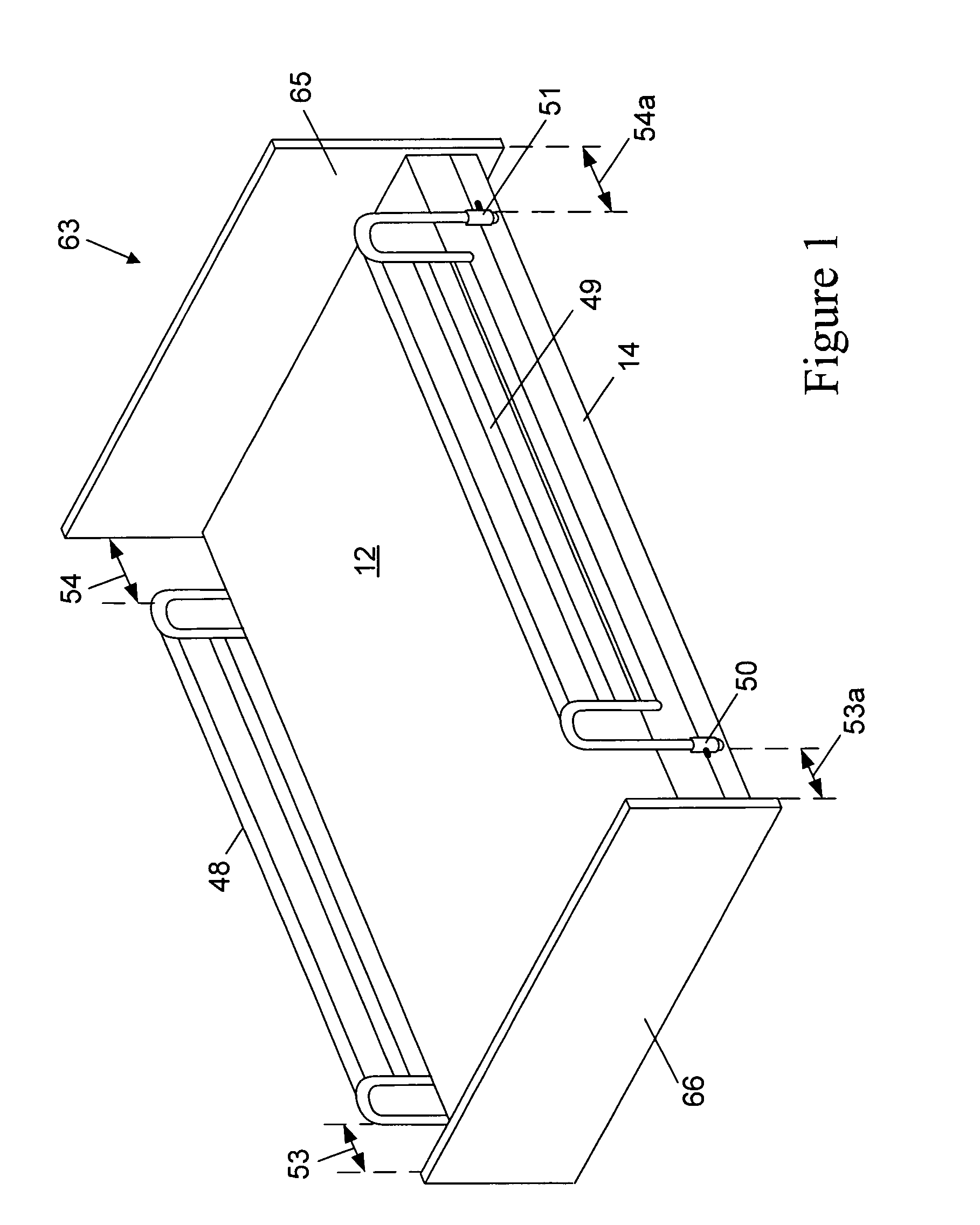
[0057]FIG. 1 is a perspective view of a bed assembly 63 comprised of a mattress 12 and foundation 14, according to the prior art. Disposed on bed assembly 63 are Bed Safety Rail (bed safety rail) assemblies 48 and 49 respectively, shown in the raised or upper operating position. Bed safety rail 48 / 49 are held in place by two adjustable lateral supports 50 and 51, respectively. Lateral supports 50 / 51 extend at least the width of mattress 12 and are disposed between mattress 12 and foundation 14. In the lowered or down configuration, the bed safety rail 48 / 49 are irrelevant to patient safety as the patient (not shown) is generally out of bed when the bed safety rail 48 / 49 are in this configuration. These prior art bed safety rail assemblies are generally manufactured of metal but could be made of any material and be in any configuration or shape of those bed safety rail assemblies currently available on the open market.

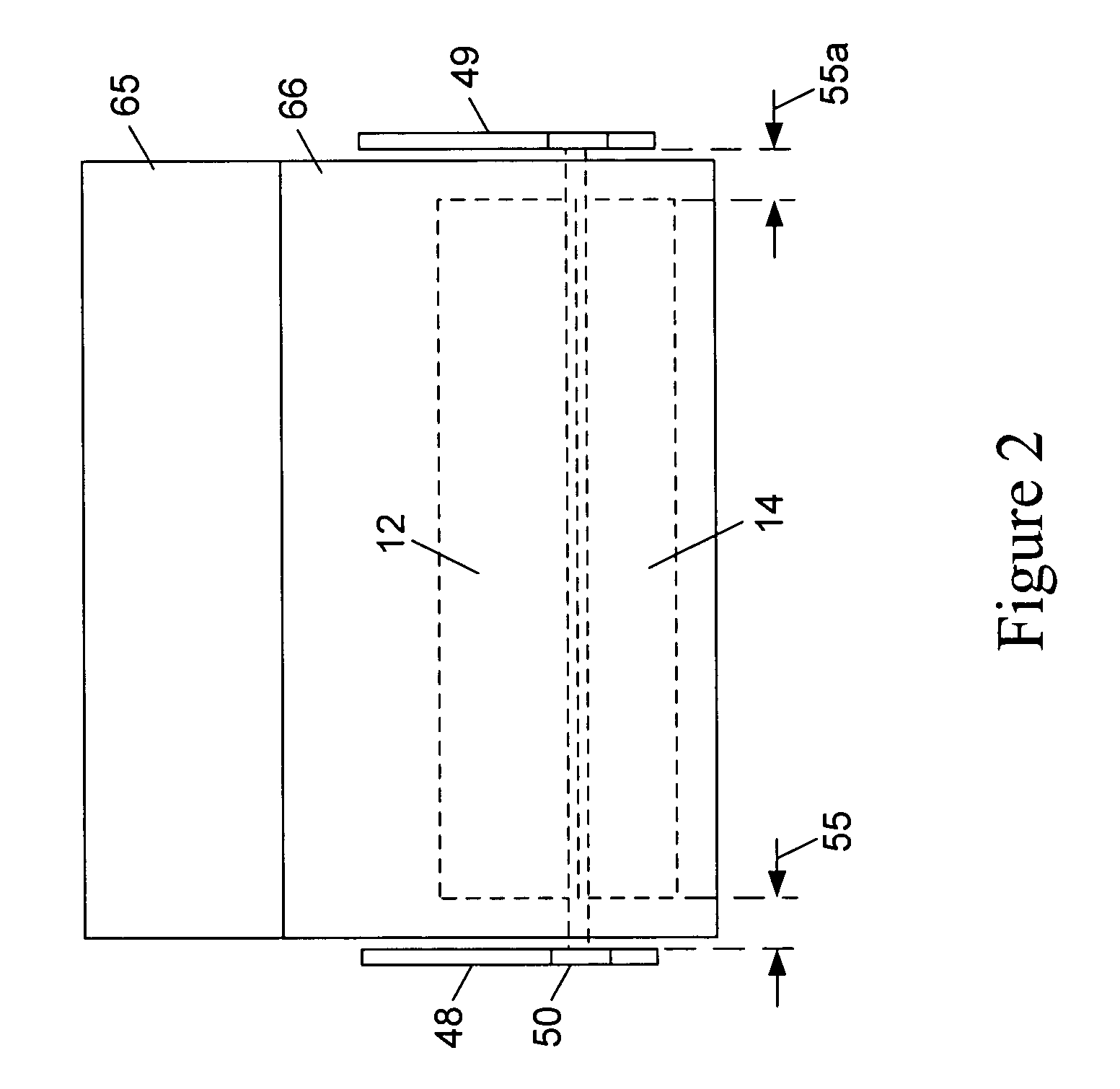
[0058]Referring to FIG. 1, the length of bed safety rail assemblie...


PUM


Abstract

A safety apparatus for a bed comprised of two safety panels and a cover. Each safety panel comprises a horizontal stabilizer and vertically-extending panel of a synthetic polymeric material with a density of from about 1 to about 10 pounds per cubic foot. The width of the stabilizer is less than about 20 per cent of the width of the mattress. Disposing the horizontal stabilizer underneath a mattress secures said the vertically-extending panel in a substantially-vertical orientation along a side of said bed. Another embodiment comprises the foregoing side panel safety apparatus in combination with a safety rail of said bed, further comprising said safety rail; wherein said horizontal stabilizer blocks a person in said bed from moving a part of said person's body into contact with said safety rail such that said body part becomes entrapped from said contact. Another embodiment comprises movable vertical sections.

Description

[0001]This patent application is a continuation-in-part of U.S. Ser. No. 10 / 904,144 (filed Oct. 26, 2004) now U.S. Pat. No. 7,127,755 claiming the benefit of provisional application U.S. Ser. No. 60 / 514,797 (filed on Oct. 27, 2003). The entire disclosures of said applications are incorporated by reference into this specification.BACKGROUND OF THE INVENTION[0002]Patients in hospitals or long-term care facilities often reside in beds disposed between safety rails. Although the use of these safety rails provides some degree of protection against the risk of the patient falling off the bed, these safety rails present their own safety concerns. In some situations, patients prefer to lower the bed rails to increase comfort, disengaging the safety feature and its protective effects.[0003]Patients, especially elderly or “developmentally disabled” patients, frequently self-inflict injuries by trapping their heads, buttocks, legs, feet, hands, arms, torso, or other body parts between the safe...

Claims


Application Information

Patent Timeline
Patent Type & Authority Patents(United States)
IPC IPC(8): A47C21/08
CPCA47C21/08A47C31/10A61G7/0507
Inventor DILIBERTO, JR., SAMUEL L.
Owner DILIBERTO JR SAMUEL L
Why Eureka
Try Eureka