Audio player

a technology of audio player and auxiliary data, which is applied in the field of digital signal processing techniques, can solve the problems of difficult to precisely synchronize between the audio data and the auxiliary data, high possibility, and track management might be wrongly performed in the external equipment, so as to prevent overflow and underflow, prevent sound deterioration, and prevent error recording in the equipment to which the audio player is connected

Active Publication Date: 2007-07-24
SOCIONEXT INC
View PDF3 Cites 0 Cited by
  • Summary
  • Abstract
  • Description
  • Claims
  • Application Information

AI Technical Summary

Benefits of technology

[0006]It is therefore an object of the present invention to solve the above-described problems and provide an audio player which includes an interface capable of specifying an IEC output mode and thus achieves general versatility.
[0008]In the audio player of the present invention, a sub-Q data table is managed so that overflow and underflow thereof are prevented. Also, an IEC output mode is changed at a time when audio processing is performed and at a time when dubbing is performed. Thus, sound deterioration, error recording in equipment to which the audio player is connected, and the like can be prevented. Moreover, a method for outputting an IEC output can be externally selected, so that a system with general versatility can be achieved.

Problems solved by technology

Accordingly, it is difficult to precisely synchronize between the audio data and the auxiliary data and then output the synchronized data in the IEC format again.
Therefore, when an output of the audio player is used with some external equipment connected thereto for the purpose of dubbing, track management might be wrongly performed in the external equipment.
In the above-described known system, when sub-Q data in user data is processed in receiving digital audio from the outside, it is highly possible that sound deterioration occurs.
Therefore, in the known system, when the audio player is used for dubbing of a music CD, a problem in which a detection point between tracks varies in receiver equipment arises.

Method used


Image

  • Audio player
  • Audio player
  • Audio player

Examples


Embodiment Construction

[0015]Hereafter, embodiments of the present invention will be described with reference to the accompanying drawings.

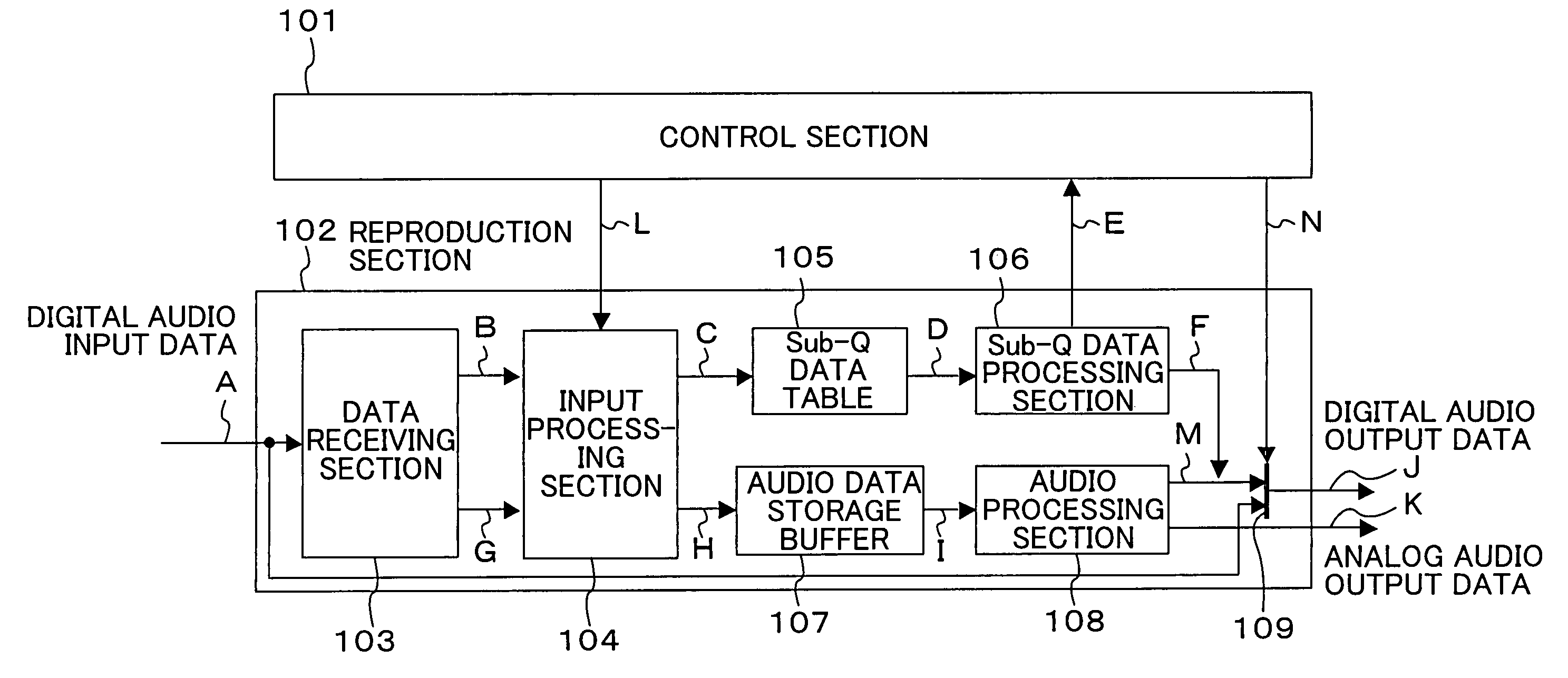
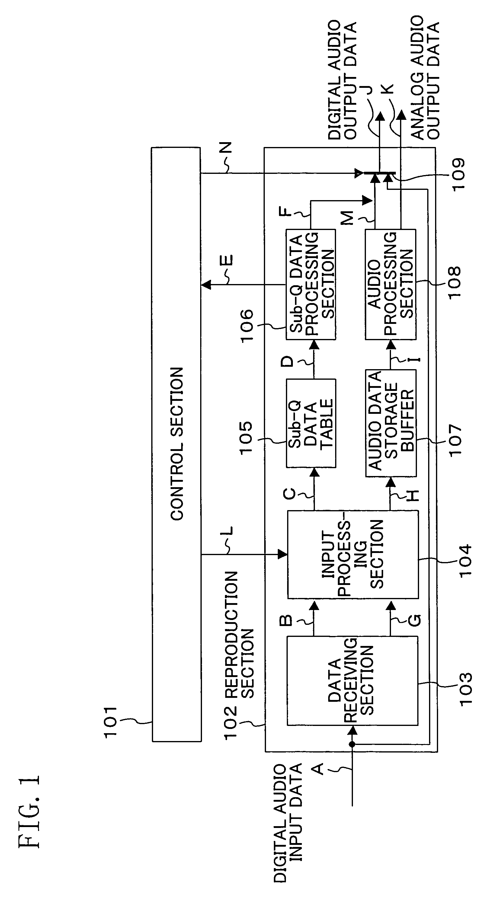
[0016]FIG. 1 is a block diagram illustrating an exemplary configuration of an audio player according to the present invention. The audio player of FIG. 1 includes broadly two parts, i.e., a control section 101 and a reproduction section 102. The reproduction section 102 includes a data receiving section 103, an input processing section 104, a sub-Q data table 105, a sub-Q data processing section 106, an audio data storage buffer 107, an audio processing section 108 and a switch 109. A denotes digital audio input data. Each of B, C, D, E and F denotes sub-Q data. Each of G, H and I denotes audio data. J denotes digital audio output data. K denotes analog audio output data. L denotes a threshold control signal. M denotes audio-processed digital audio output data. N denotes a digital audio output switching control signal.

[0017]The data receiving section 103 extracts audio...


PUM

PropertyMeasurementUnit
timeaaaaaaaaaa
thresholdaaaaaaaaaa
sizeaaaaaaaaaa

Abstract

When underflow of a sub-Q data table occurs, a sub-Q data processing section does not read and output sub-Q data but outputs only audio data. Moreover, to achieve consistency between audio data and the sub-Q data in terms of buffer management, an input processing section includes respective counters for managing respective input data amounts of the audio data and the sub-Q data. Then, the input processing section executes management so that overflow and underflow of the sub-Q data table are suppressed as much as possible and a switch changes an IEC output mode at a time of audio processing and a time of dubbing. Thus, sound deterioration, and error recording in equipment to which the audio player is connected, and the like can be prevented.

Description

BACKGROUND OF THE INVENTION[0001]The present invention relates to digital signal processing techniques in a broad sense, and particularly relates to a method for managing audio data and sub-Q data in equipment capable of receiving a digital audio from the outside and a method for outputting such data.[0002]In a music CD, sub-Q data which is different data from audio data is recorded in a sub-coded Q channel. Such sub-Q data is used for reproduction time display and pause detection in dubbing. Conventionally, a system in which in reproducing a music CD, audio data and sub-Q data are synchronized and then output has been known (see Japanese Laid-Open Patent Publication No. 2001-155432).[0003]In recent years, equipment capable of handling not only optical disc reproduction but also external digital audio input has been widely spread. Digital audio from the outside is received in the format defined in IEC 60958 or IEC 61937. When some audio processing is performed to the received data, ...

Claims


Application Information

Patent Timeline
Patent Type & Authority Patents(United States)
IPC IPC(8): G11B15/52G06F17/00
CPCG11B27/034G11B27/10G11B27/3063G11B2220/2545
Inventor SUGUTA, SEIGOKAWASHIMA, ICHIROGOTO, HIROYUKI
Owner SOCIONEXT INC
Why Eureka
Try Eureka