Bobbin changer apparatus for sewing machine

a technology for changing bobbins and sewing machines, applied in sewing apparatuses, loop takers, textiles and paper, etc., can solve the problems of high cost, high labor intensity, and a large amount of time and labor in the manufacture of component parts

Inactive Publication Date: 2007-03-15
TOKAI IND SEWING MACH CO LTD +1
View PDF5 Cites 0 Cited by
  • Summary
  • Abstract
  • Description
  • Claims
  • Application Information

AI Technical Summary

Benefits of technology

[0008] In view of the foregoing, it is an object of the present invention to provide a bobbin changer apparatus of a novel construction with various improvements over the conventional counterparts. It is another object of the present invention to provide an easy-to-use bobbin changer apparatus which can readily deal with a difference in traveling distance of a bobbin grasping device. It is still another object of the present invention to provide a bobbin changer apparatus which can be detached and reattached without cumbersome operation even where it is applied to a dividable sewing table.

Problems solved by technology

Where such a bobbin changer is not used, the human operator has to get into under the sewing table and manually change bobbin cases in the rotary hook on the hook base, which is very cumbersome.
With the aforementioned conventional technique, where the guide plate has integrally incorporated therein the mechanisms for changing the orientation of the chuck section at the opposite ends of the transfer stroke, it is necessary to separately make guide plates, having integrally incorporated therein the mechanisms for changing the orientation of the chuck section at the opposite ends of the transfer stroke, in various sizes and constructions suited for various types of sewing machines, which tends to take a lot of time and labor in manufacturing of component parts and therefore result in high cost.
Such operation tends to take a lot of time and labor.
Particularly, because positioning of the bobbin grasping device relative to the rotary hook and bobbin stock section depends on the positions of the orientation-changing mechanisms in the opposite end portions of the guide plate, position adjustment of the guide plate tends to be very time-consuming.

Method used


Image

  • Bobbin changer apparatus for sewing machine
  • Bobbin changer apparatus for sewing machine
  • Bobbin changer apparatus for sewing machine

Examples


Embodiment Construction

[0028] [General External Appearance of Multi-Head Embroidery Sewing Machine]

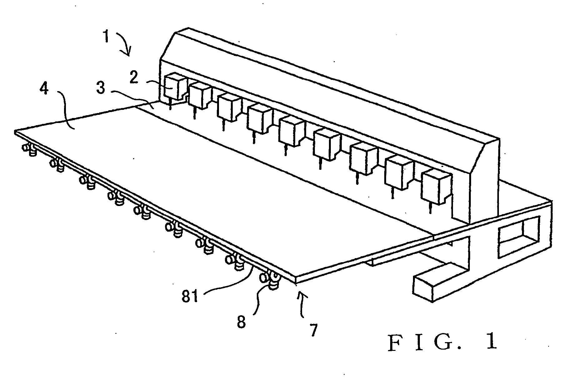
[0029]FIG. 1 is a schematic view showing an example external appearance of a multi-head embroidery sewing machine employing a bobbin changer apparatus in accordance with the present invention.

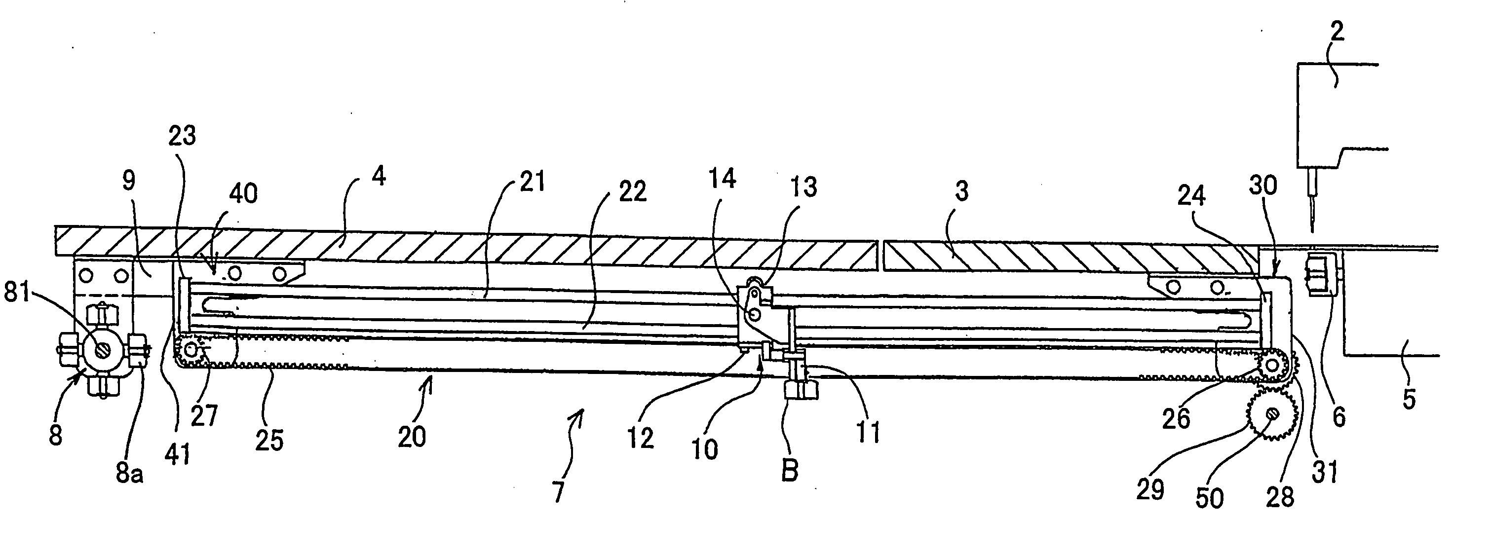
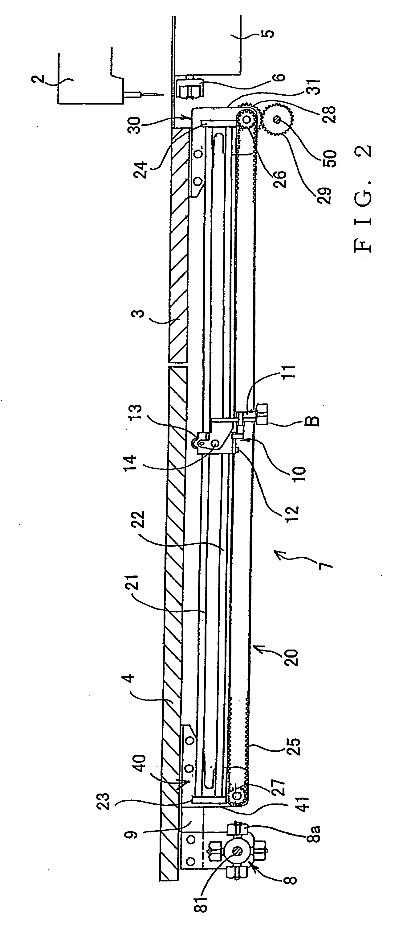
[0030] As known in the art, the multi-head embroidery sewing machine 1 at least includes a plurality of machine heads 2, rotary hook bases 5 (FIG. 2) provided beneath a main (body) sewing table 3 in corresponding relation to the machine heads 2, rotary hooks 6 (FIG. 2) provided on the individual hook bases. Extension sewing table 4 is detachably attached to a front edge portion of the main sewing table 3. Further, although not shown for simplification of illustration, an embroidery frame drive mechanism is provided on the sewing tables. Further, the bobbin changer apparatus 7 according to an embodiment of the present invention is provided for each of the rotary hooks 6 corresponding to the machine heads 2. Although the...


PUM


Abstract

Transfer mechanism (20) is provided for reciprocally transferring a bobbin grasping device (10), grasping a bobbin case (B) at the distal end of a chuck section (11), between a rotary hook (6) of a sewing machine and a bobbin stock section (8). First cam plate (31) is provided adjacent to one end for orienting the chuck section (11) toward the rotary hook (6) during the transfer, while a second cam plate (41) is provided adjacent to the other end for orienting the chuck section (11) toward the bobbin stock section (8) during the transfer. The cam plates (31, 41) are detachable from the transfer mechanism (20), and, in transportation of the machine, one of the cam plates is transported as an attachment to a main sewing table, while the other plate is transported as an attachment to an extension sewing table. The bobbin grasping device (10) includes a moving body section (13), chuck section (11), and a spring member (19) for normally biasing the chuck section toward a predetermined neutral position.

Description

TECHNICAL FIELD [0001] The present invention relates to a bobbin changer apparatus for automatically replacing a bobbin case having accommodated therein a lower thread bobbin to be mounted in a rotary hook of a sewing machine. BACKGROUND ART [0002] Lower thread change devices are arranged to, when a bobbin, contained in a bobbin case mounted in a rotary hook supported on a rotary hook base, has run out of a lower thread, automatically replace the empty bobbin case with a new bobbin case containing a bobbin with a sufficient lower thread wound thereon, and such lower thread change devices have been known as bobbin changers. In Japanese Patent Application Laid-open Publication No. 2000-157774, there is disclosed a multi-head sewing machine equipped with a plurality of machine heads, where a bobbin changer is provided for each of the machine heads (i.e., for each of the rotary hook bases) and drive mechanisms of the individual bobbin changers are drivable via a same or common drive sou...

Claims


Application Information

Patent Timeline
Patent Type & Authority Applications(United States)
IPC IPC(8): D05B57/10D05B59/04
CPCD05B59/04
Inventor TAJIMA, IKUOFUKUSHIMA, TAICHIKINOSHITA, HARUHIKO
Owner TOKAI IND SEWING MACH CO LTD
Why Eureka
Try Eureka