Friction stir spot joining device

a technology of friction stir and joining device, which is applied in the direction of soldering apparatus, manufacturing tools,auxillary welding devices, etc., can solve the problems of pin side liable to vibrate, stirring motor and power transmission mechanism cannot be solely removed or replaced, and the bearing of the linear motion guide is difficult to take out and assemble, etc., to achieve restraining vibration, reducing the burden applied to the bearing of the linear motion guide, and light in weight

Inactive Publication Date: 2010-09-28
KAWASAKI HEAVY IND LTD +1
View PDF7 Cites 0 Cited by
  • Summary
  • Abstract
  • Description
  • Claims
  • Application Information

AI Technical Summary

Benefits of technology

[0008]The present invention has been made in view of the problems of the foregoing conventional techniques, and it is therefore an object of the invention to provide a friction stir spot joining device which unitizes stirring-related members to form a stirring unit, and forms an opening in a friction stir spot joining device body (hereinafter referred to a joining device body) for housing therein the stirring unit, so that the stirring unit becomes light in weight, has a general versatility with a simple structure and can be moved with assurance, and the components thereof can be removed with ease.
[0011]With the configuration of the friction stir spot joining device according to the first aspect of the invention, a burden applied to the bearings of the linear motion guide is reduced, thereby restraining the vibration at the pin side, and the components of the stirring unit can be removed and replaced with ease, so that the friction stir spot joining device can be light in weight as a whole.
[0012]With the configuration of the friction stir spot joining device according to the second aspect of the invention, the transmission of the power from the stirring motor to the stirring shaft is assured and the linear motion guide can be disposed to approach a portion immediately under the toothed pulley, so that the generation of falling torque relative to the linear motion guide caused by stirring torque is prevented and a distance from the center of the stirring shaft to the bottom face of the joining device body can be minimized, thereby restraining the friction stir spot joining device from increasing in height.

Problems solved by technology

However, since the integrated stirring-related members are entirely contained in the friction stir spot joining device body, when performing maintenance or assembly of the stirring-related members, the stirring-related members are difficult to take out and assemble, and the stirring motor and the power transmission mechanism for the stirring motor cannot be solely removed or replaced.
Further, since the bearings of the linear motion guide are fixed to the lower portion of the power transmission mechanism behind thereof, a large burden is applied to the bearings of the linear motion guide, causing a problem that the pin side is liable to vibrate and so forth.

Method used


Image

  • Friction stir spot joining device
  • Friction stir spot joining device
  • Friction stir spot joining device

Examples


first example

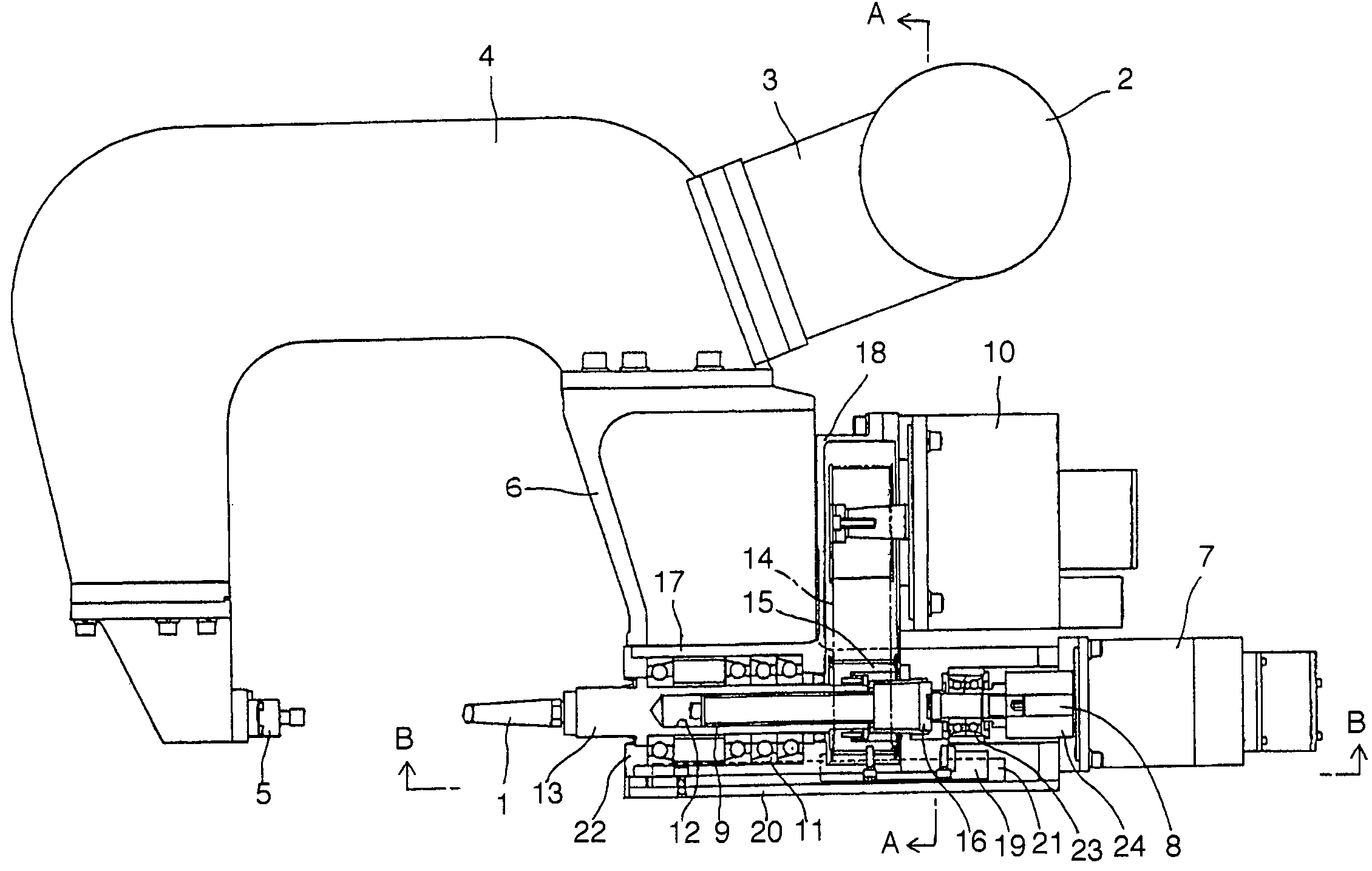
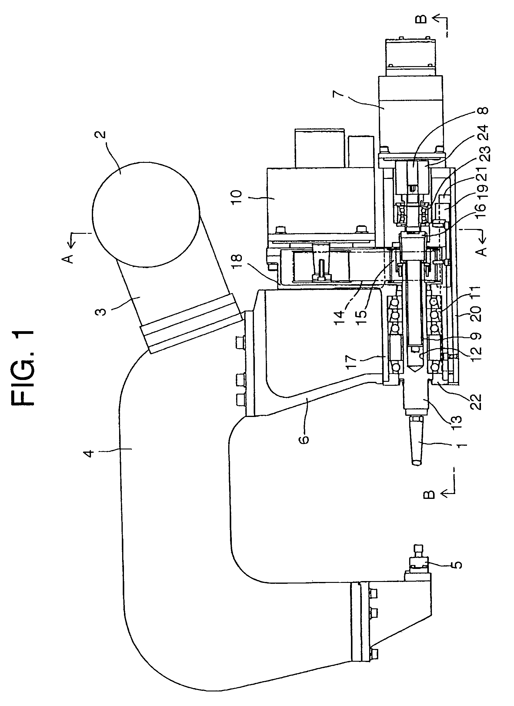
[0018]In the friction stir spot joining device, the pin 1 is inserted in a joining point of an object to be joined (not shown), and a part of the object to be joined is softened and stirred by the frictional heat caused by rotation of the pin 1, thereby performing spot joining. The friction stir spot joining device is roughly structured as follows.

[0019]A holding jig 5 for holding the object to be joined is disposed at the tip end of a fixed arm 4 which is fitted to a wrist 2 of a robot by way of a bracket 3, and a joining device body 6 is fixedly secured to a rear end portion of the fixed arm 4. The pressure application motor 7 is fixedly secured to a rear end portion of the joining device body 6 and the screw shaft 9 is fixedly secured to an output shaft 8 of the pressure application motor 7.

[0020]The stirring motor 10 for rotating the pin 1, a stirring shaft 13 having the pin 1 at the tip end, and supported by the bearings 11 and provided with the hole 12 at the center through wh...

second example

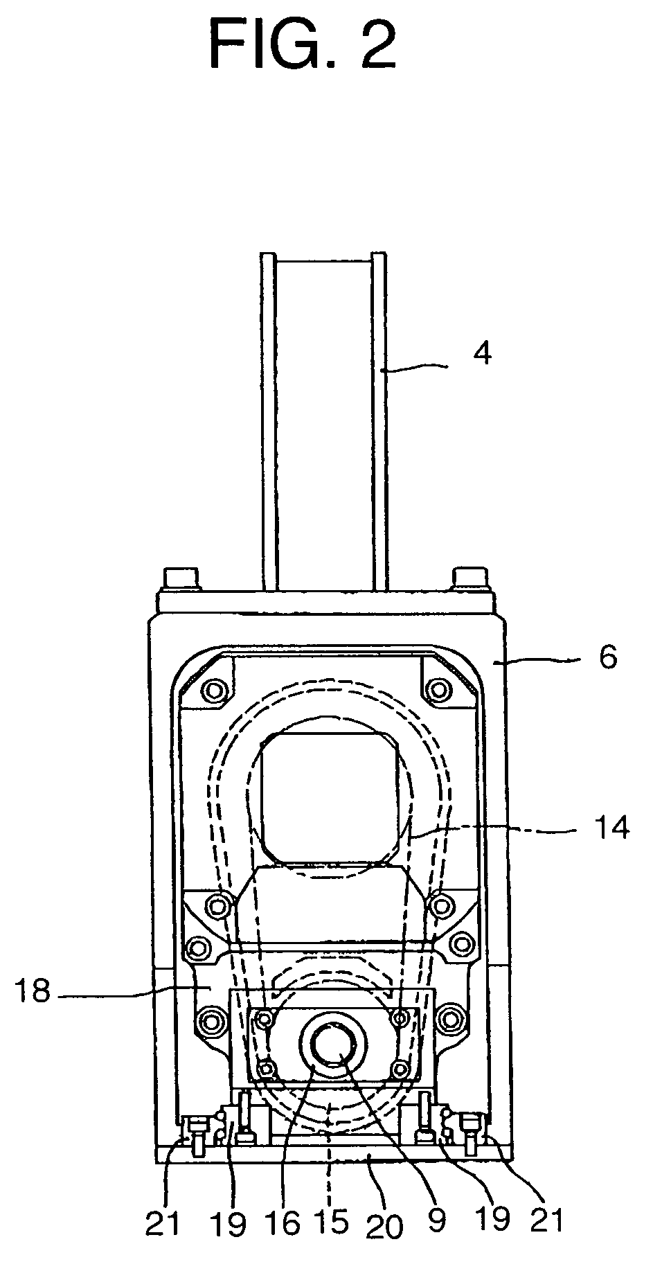
[0030]The power transmission mechanism 14 according to the first example is configured to be comprised of a toothed pulley 15 and a toothed belt, and lateral split type bearings 19, 19 of a linear motion guide are disposed immediately under the toothed pulley 15.

[0031]As a result, power transmission from a stirring motor 10 to a stirring shaft 13 is performed with assurance, and the linear motion guide can be disposed at a portion closer than a portion immediately under the toothed pulley 15, so that falling torque relative to the linear motion guide caused by stirring torque is not generated. Further, it is possible to minimize a distance from the center of the stirring shaft 13 to a bottom plate 20 of a joining device body 6.


PUM

PropertyMeasurementUnit
frictional heataaaaaaaaaa
pressureaaaaaaaaaa
lengthaaaaaaaaaa

Abstract

There is provided a friction stir spot joining device wherein stirring-related members are unitized to form a unitized stirring unit and an opening is formed in a friction stir spot joining device body for housing the unitized stirring unit therein. A stirring motor, a stirring shaft and a power transmission mechanism are unitized to form a stirring unit, and bearings of a linear motion guide are fixed to the stirring unit immediately under the stirring unit, and a ball nut is fixed to the back face of the stirring unit, wherein the friction stir spot joining device body is opened to form the opening at a rear upper portion through which the stirring unit is caused to move inside thereof.

Description

FIELD OF THE INVENTION[0001]The invention relates a friction stir spot joining device for softening and stirring an object to be joined by frictional heat generated by rotation of a pin so as to perform spot joining, and provided with a stirring motor for rotating the pin and a pressure application motor for driving the pin to be moved straight.BACKGROUND OF THE INVENTION[0002]There has been conventionally a friction stir spot joining device for softening and stirring an object to be joined by frictional heat generated by rotation of a pin so as to perform spot joining, and provided with a stirring motor for rotating the pin and a pressure application motor for driving the pin to be moved straight (for example, see Patent Document 1).[0003]There has been also a friction stir spot joining device for softening and stirring an object to be joined by frictional heat generated by rotation of a center pin and a shoulder pin so as to perform spot joining, and provided with a stirring motor...

Claims


Application Information

Patent Timeline
Patent Type & Authority Patents(United States)
IPC IPC(8): B23K20/12
CPCB23K20/125B23K20/1265B23K20/1245B23K37/02
Inventor FUKUHARA, KAZUMIKUMAGAI, MASAKIFUKUDA, TOSHIHIKOSATO, YOSHIOAOKI, KENTA
Owner KAWASAKI HEAVY IND LTD
Why Eureka
Try Eureka