
Method and apparatus for increasing fuse programming yield through preferred use of duplicate data

a technology of duplicate data and programming yield, applied in the field of encoding a bit string, can solve the problems of increasing the resistance of the integrated circuit, the difficulty of customizing the test and repair of complex integrated circuits in an automated manufacturing test environment, and the need to automatically repair the defective memory elements in large arrays of memory on the integrated circuit chip

Active Publication Date: 2007-07-31
MARVELL ASIA PTE LTD
View PDF9 Cites 51 Cited by
  • Summary
  • Abstract
  • Description
  • Claims
  • Application Information

AI Technical Summary

Benefits of technology

The present invention addresses the problem of replacing defective memory elements in integrated circuits. It uses fuses to program spare memory elements to replace defective ones. A binary string is generated to indicate which spare memory elements replace which defective ones. The number of fuses available to program the string is determined based on the number of bits in the string. The fuses can record one or more bits of the string, and a format indication is recorded to indicate which bits were recorded in which fuses. This invention allows for efficient replacement of defective memory elements in integrated circuits.

Problems solved by technology

The customization, test and repair of complex integrated circuits in an automated manufacturing test environment are challenging problems.
One issue that arises in this context is the need to automatically repair defective memory elements in large arrays of memory on integrated circuit chips.
This current disturbs the polysilicon link, dramatically increasing its resistance.
One difficulty with e-fuses is that their programming is not entirely reliable.
This unreliability presents a particularly significant problem, because this kind of failure in the programming of even a single e-fuse on a chip, if uncorrectable, may spoil the chip.

Method used


Image

  • Method and apparatus for increasing fuse programming yield through preferred use of duplicate data
  • Method and apparatus for increasing fuse programming yield through preferred use of duplicate data
  • Method and apparatus for increasing fuse programming yield through preferred use of duplicate data

Examples


Embodiment Construction

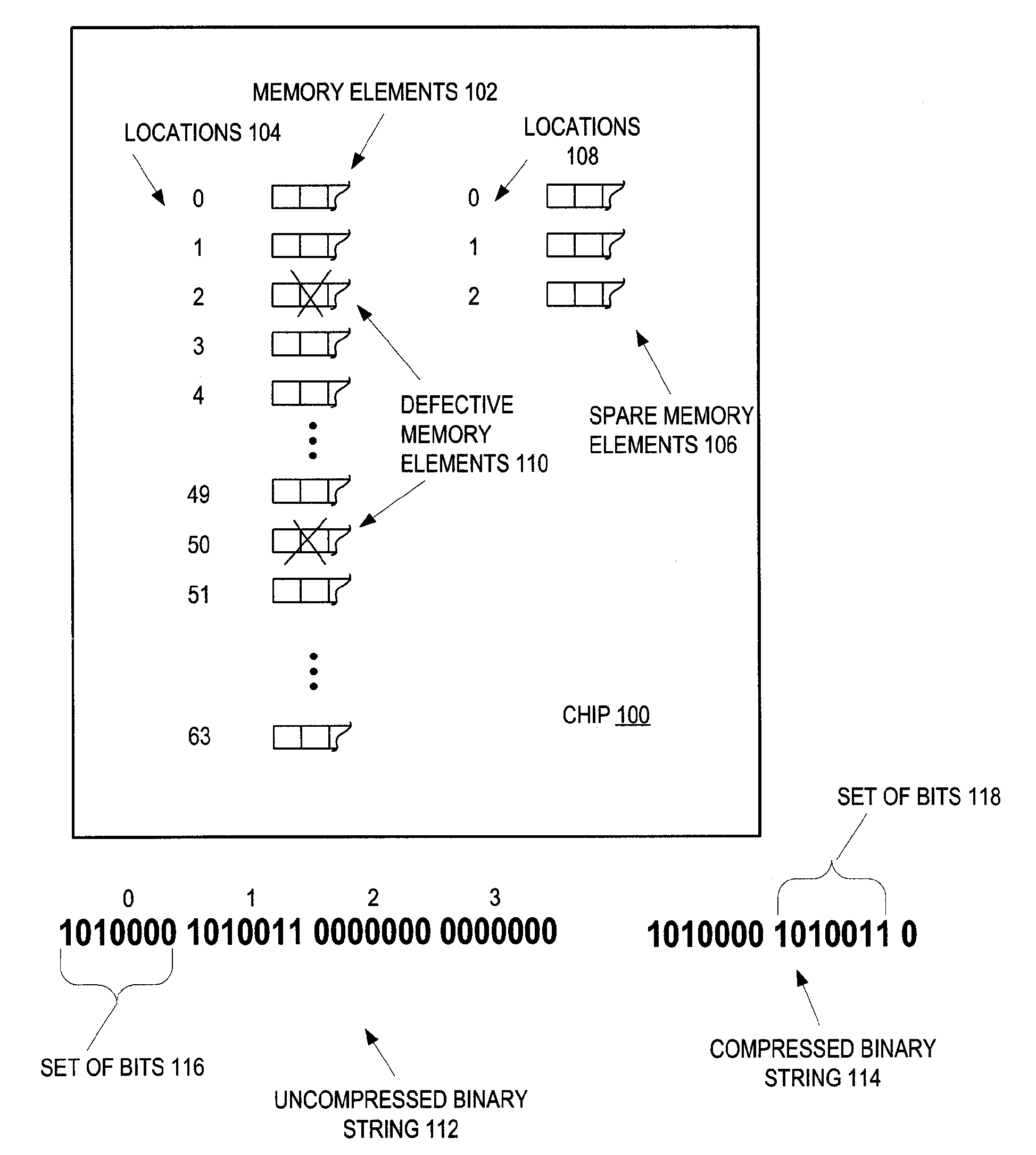
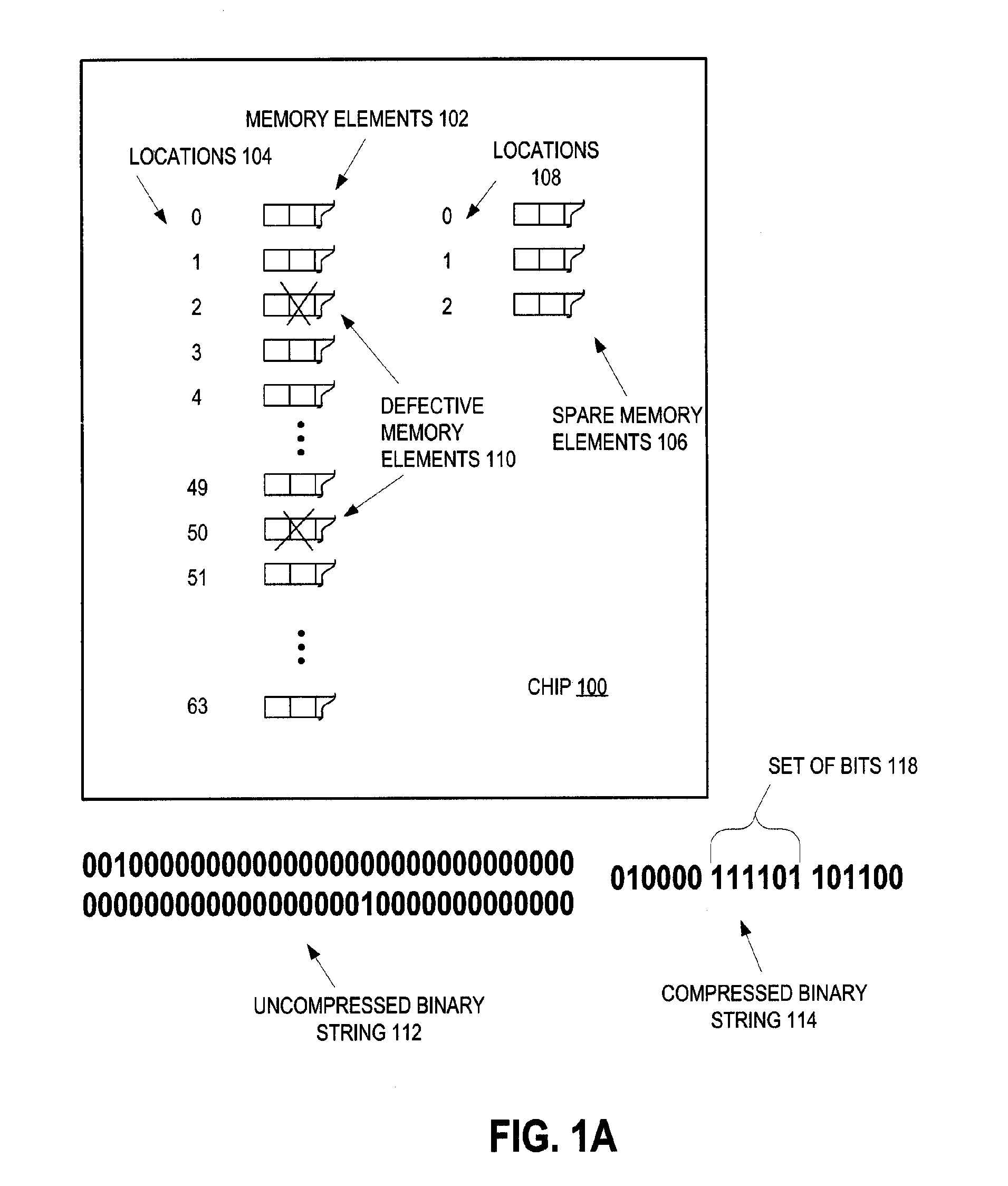
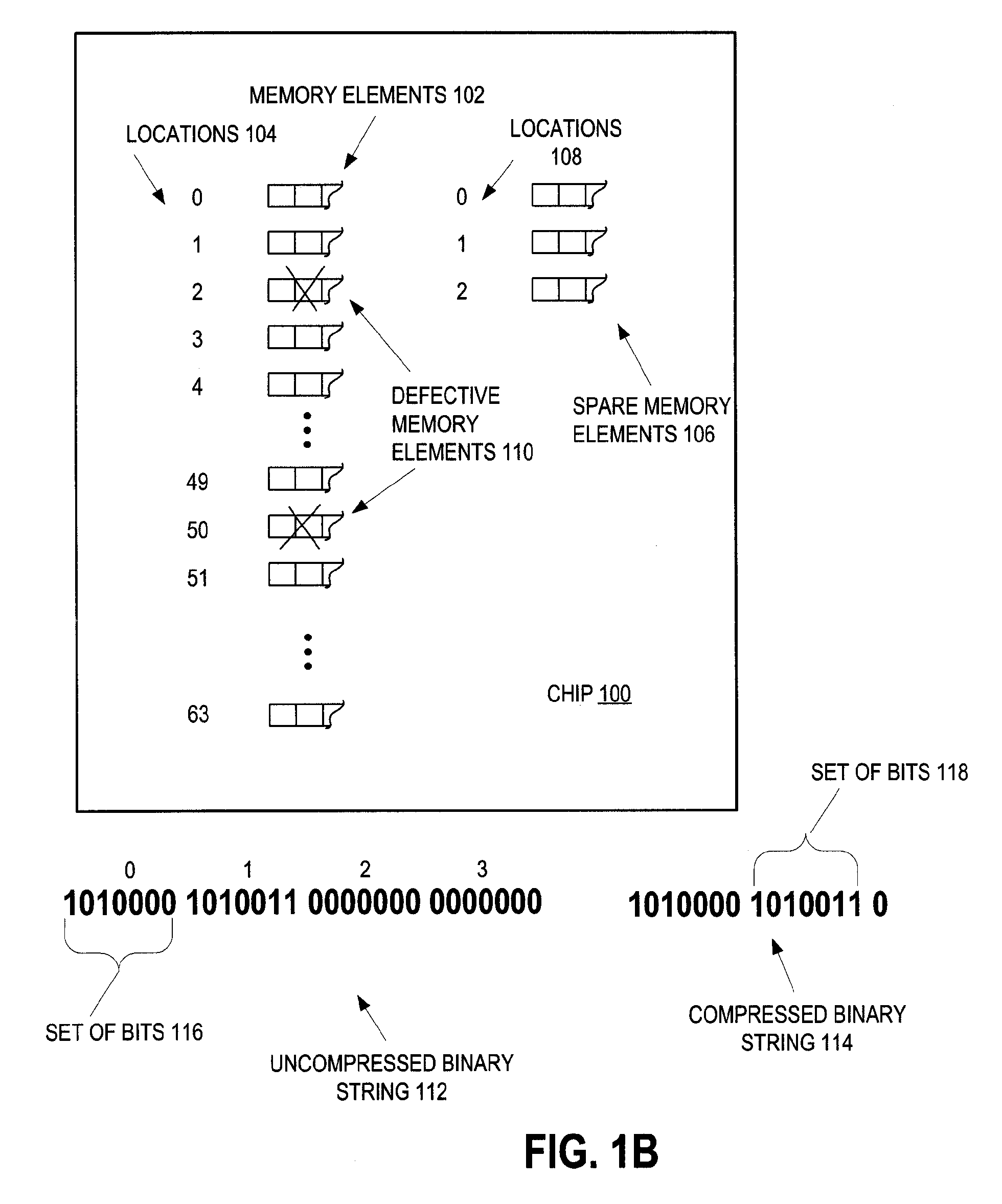
[0029]Referring now to FIG. 1A, an integrated circuit chip 100 is shown, according to an embodiment of the present invention. For simplicity of explanation, chip 100 is shown with only sixty-four memory elements 102. (It should, of course, be understood that a preferred chip 100 may have more on the order of tens of thousands memory elements 102.) Each memory element 102 has a number of memory cells, as shown. That is, each memory element 102 may be a word line, each having about one thousand memory cells, for example. The sixty-four memory elements 102 are shown at locations 104, numbered 0 through 63. Chip 100 also includes four spare memory elements 106, at locations 108, numbered 0 through 3, for replacing defective ones of memory elements 102. (It should, of course, be understood that a preferred chip 100 may have more on the order of several thousand spare memory elements 106.)

[0030]In the illustrated instance, testing of memory elements 102 has revealed that the ones of memor...


PUM


Abstract

Integrated circuit memory is tested to discover defective memory elements. To replace the defective memory elements, spare memory elements are selected and a string is generated to indicate which ones of the spares replace which ones of the defective memory elements. The number of bits of the string depend upon how many of the memory elements are defective. Although a certain number of the memory elements are defective, which determines the number of the string bits, nevertheless, a number of fuses to program on the integrated circuit is determined responsive to how many fuses are available for programming relative to the number of the binary string bits. That is, if more fuses are available than a certain threshold number relative to the number of string bits (as is preferred), then more than the threshold number are programmed. If not, then only that certain threshold number of fuses are programmed.

Description

CROSS-REFERENCE TO RELATED APPLICATION[0001]This application is related to the following U.S. patents, which are hereby incorporated herein by reference:[0002]U.S. Pat. No. 6,856,569, Nelson, et al., Feb. 15, 2005, “Method and system for merging multiple fuse decompression serial bitstreams to support auxiliary fuseblow capability;” and[0003]U.S. Pat. No. 6,768,694, Anand, et al., Jul. 27, 2004, “Method of electrically blowing fuses under control of an on-chip tester interface apparatus.”BACKGROUND OF THE INVENTION[0004]1. Field of the Invention[0005]The present invention generally relates to testing and replacing defective memory elements through the use of fuses. More specifically, the invention relates to encoding of a bit string in the fuses and to subsequent decoding of the fuses.[0006]2. Description of the Related Art[0007]The customization, test and repair of complex integrated circuits in an automated manufacturing test environment are challenging problems. One issue that ar...

Claims


Application Information

Patent Timeline
Patent Type & Authority Patents(United States)
IPC IPC(8): G11C29/00
CPCG11C17/165G11C29/027G11C29/4401G11C29/72
Inventor ANAND, DARREN LANEOUELLETTE, MICHAEL RICHARDZIEGERHOFER, MICHAEL ANTHONY
Owner MARVELL ASIA PTE LTD
Learn More