Hair clipper with pivot head

a technology of electric hair clippers and pivot heads, which is applied in the direction of belts/chains/gears, metal working apparatuses, belts/chains/gears, etc., can solve the problems of complex and expensive multiple gear systems of the weinrauch transmission mechanism

Active Publication Date: 2007-08-07
CHURCH & DWIGHT CO INC
View PDF17 Cites 32 Cited by
  • Summary
  • Abstract
  • Description
  • Claims
  • Application Information

AI Technical Summary

Benefits of technology

[0024]FIG. 3 is a cross-sectional view of the forward portion of the handle section and the rear portion of the head section showing the control button in the engaged position

Problems solved by technology

However, the Weinrauch transmission mechanism employes a multiple gear system that is far too comp

Method used


Image

  • Hair clipper with pivot head
  • Hair clipper with pivot head
  • Hair clipper with pivot head

Examples


Embodiment Construction

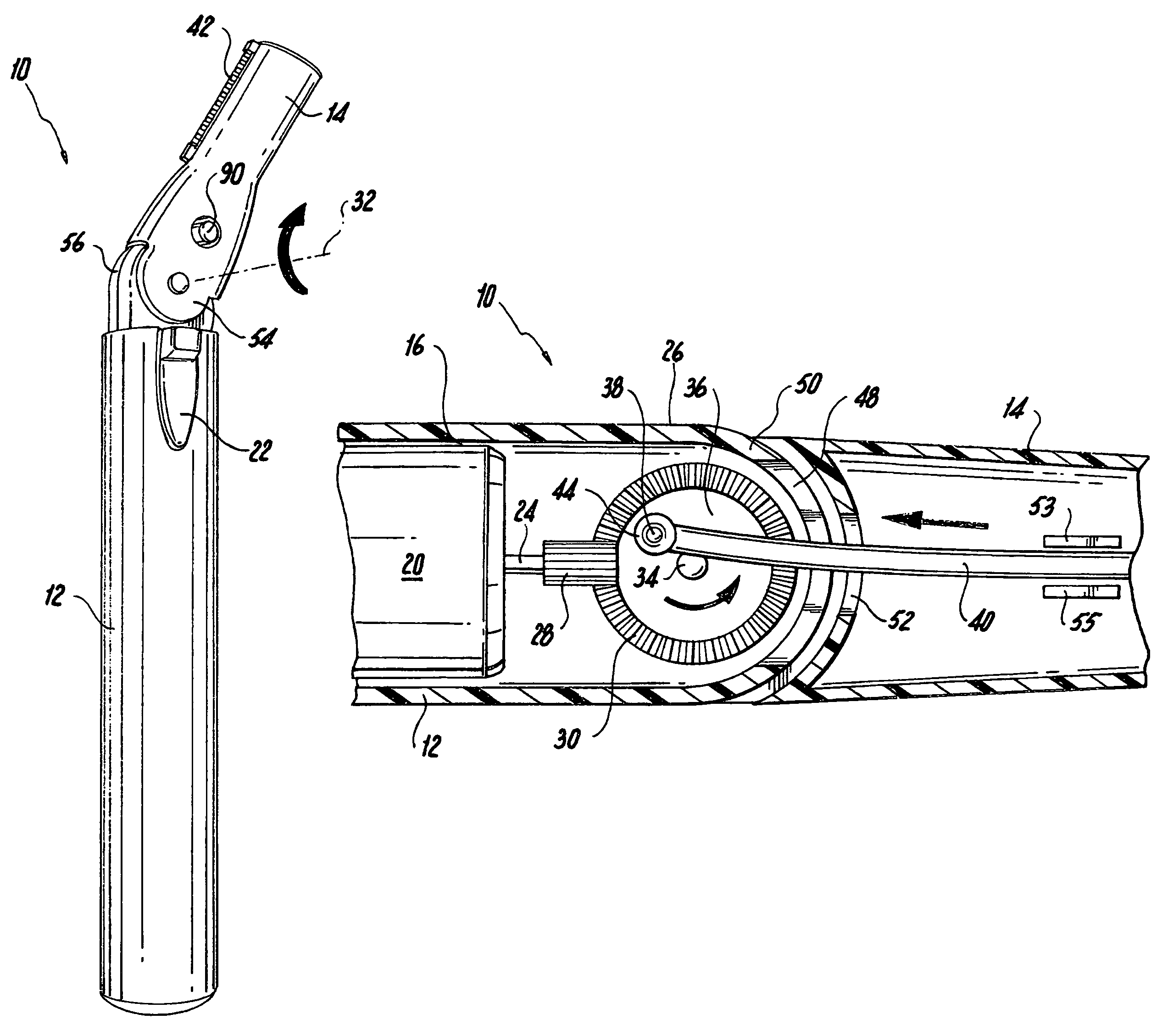
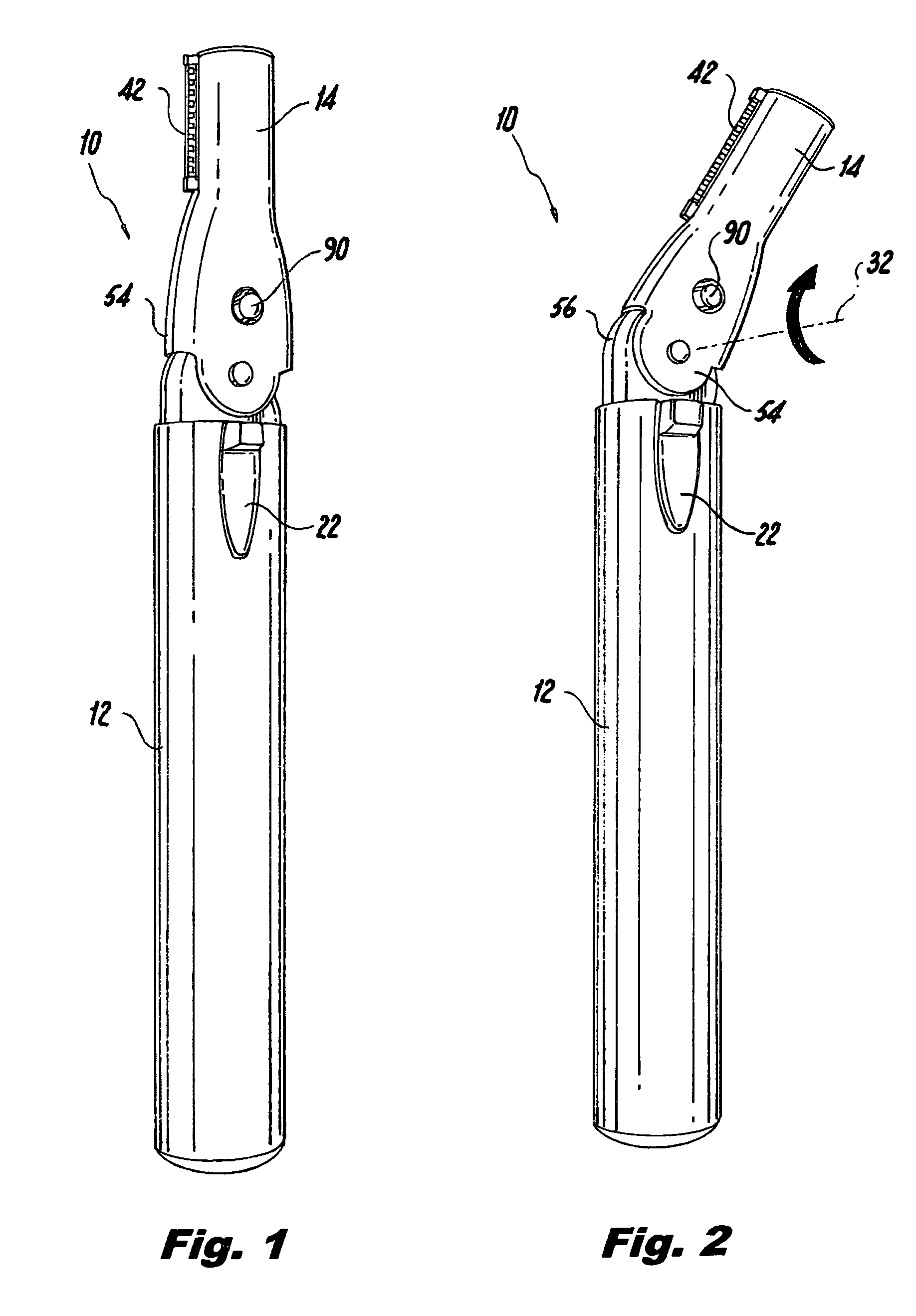
[0030]As seen in the drawings, the hair clipper of the present invention includes a generally cylindrical housing 10 made of lightweight metal or plastic material. Housing 10 includes a handle section 12 and a head section 14.

[0031]Handle section 12 is hollow and includes a recess 16 into which a battery (not shown) and a motor 20 are received. The battery is connected to motor 20 through a slide-type power switch 22 accessible from the exterior of the handle section 12 of housing 10.

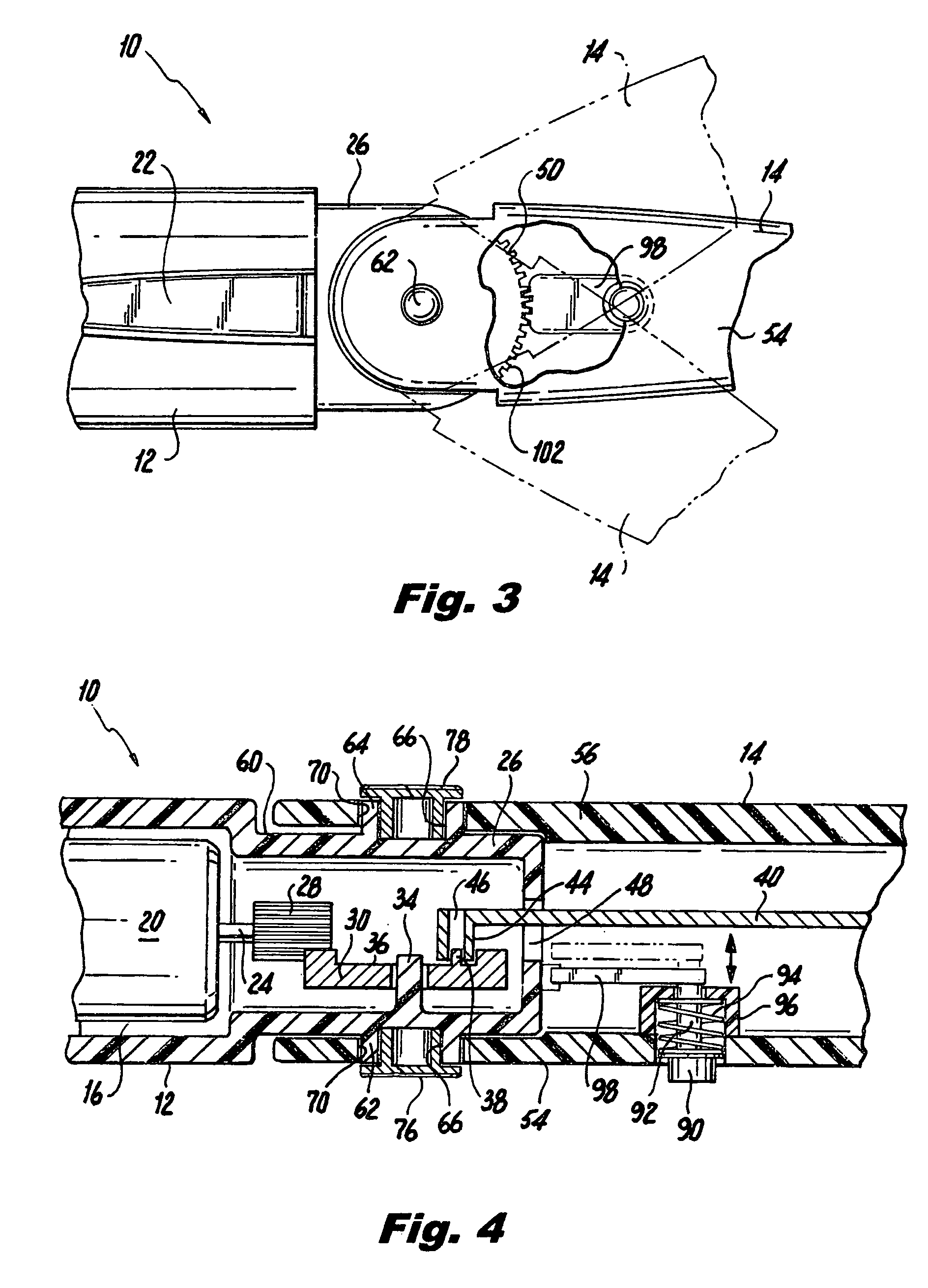
[0032]As is best seen in FIGS. 4, 7 and 8, motor 20 has a rotatable output shaft 24 that extends into the forward portion 26 of handle section 12 along the axis of housing 10. A first drive gear 28 is fixedly mounted on the end of shaft 24.

[0033]The teeth of a second drive gear 30 mesh with the teeth of the first drive gear 28. The second drive gear 30 is mounted within forward portion 26 for rotation about an axis 32, defined by a shaft 34 which extends from the interior wall of forward portion 26. Gea...


PUM


Abstract

The clipper has a cylindrical housing including a handle containing a battery and motor and a head pivotally mounted on the handle. The head carries a stationary blade and a reciprocating blade. Motion is transmitted from the motor to the reciprocating blade through a flexible rod. One end of the rod is connected to a protrusion offset from the axis of a gear connected to the output shaft on the motor. The other end of the arm carries the reciprocating blade. A control button is provided on the head. The control button can be manipulated to disengage the handle, to permit the head to be pivoted relative to the handle.

Description

CROSS-REFERENCE TO RELATED APPLICATIONS[0001]Not ApplicableSTATEMENT REGARDING FEDERALLY SPONSORED RESEARCH OR DEVELOPMENT[0002]Not ApplicableREFERENCE TO A “SEQUENCE LISTING”, A TABLE, OR A COMPUTER Program Listing Appendix Submitted on Compact Disc[0003]Not ApplicableBACKGROUND OF THE INVENTION[0004]1. Field of the Invention[0005]The present invention relates to a lightweight, portable electric hair clipper and more particularly to such a hair clipper in which the head section is mounted on the handle section such that it can be pivoted relative to the handle section.[0006]2. Description of Prior Art Including Information Disclosed Under 37 CFR 1.97 and 1.98[0007]Many types of electrically driven hair cutting instruments including stationary blade elements and movable blade elements are known. Those hair cutters can be broadly characterized into those in which the moveable blade elements reciprocate relative to the stationary blade element in a direction perpendicular to the axis ...

Claims


Application Information

Patent Timeline
IPC IPC(8): B26B19/04
CPCB26B19/02B26B19/063Y10T74/18208Y10T74/18248
Inventor KHUBANI, ANAND
Owner CHURCH & DWIGHT CO INC
Why Eureka
Try Eureka