Clamping device for stainless steel sinks

Inactive Publication Date: 2007-08-07
BRANNEN RUSSELL H
View PDF5 Cites 40 Cited by
  • Summary
  • Abstract
  • Description
  • Claims
  • Application Information

AI Technical Summary

Benefits of technology

[0008]It is therefore an object of the present invention to provide a clamping device for stainless steel sinks w

Problems solved by technology

Because the workload at the sink area is intense and very repetitious, there is always a plurality of cooking equipment, detergents, sanitizers, and other items in and around the sink area.
However, wall-mounted racks require holes that create potential portals of entry for insects and rodents and aesthetically damage the walls.
The floors are especially important to safety since greasy floors can cause a slip and fall, and thus results in possible injury and liability issues for the business operators.
Regulatory agencies quite often deduct points for hoses left openly exposed on the floor, as it is a cleaning hindrance and a walki

Method used


Image

  • Clamping device for stainless steel sinks
  • Clamping device for stainless steel sinks
  • Clamping device for stainless steel sinks

Examples


Example

[0023]While the specification concludes with claims particularly pointing out and distinctly claiming the subject matter which is regarded as the invention, the invention will now be described by reference to the following description of preferred embodiment taken in conjunction with the accompanying drawings.

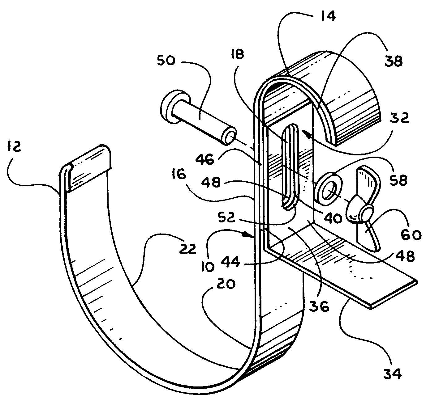
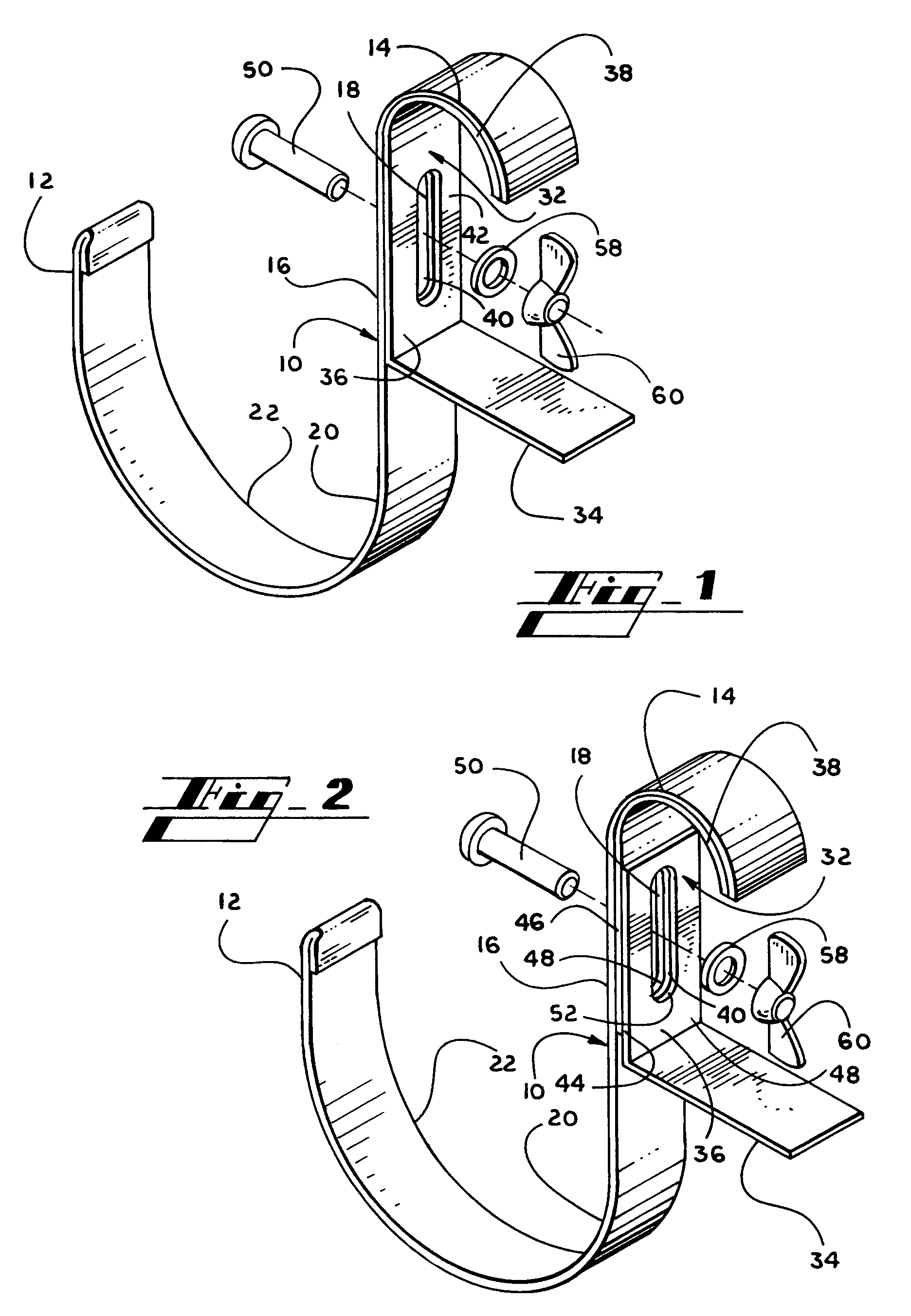
[0024]Referring now to the drawings, and particularly FIGS. 1 and 2, there is shown an isometric view of a clamping device for stainless steel sinks generally designated by the reference 10 constructed according to the principles of the present invention. The present device, in its broadest context, has as its components a hanger bracket 12, a compression gib 32, and fastening means 50. The hanger bracket 12 is further defined by a front 16, a supporting member 20, and a crispate top 14. Additionally, the front 16 has an elongated vertical slot 18 which extends the length of the front 16 along a longitudinal center axis. The supporting member 20 is attached to the lower portion...


PUM


Abstract

A clamping device for stainless steel sinks having rolled rim edges used for suspension of weighted items from a sink's rolled rim edge for better organization around the sink work area comprising, a hanger bracket, a compression gib, and a fastening means. The hanger bracket is further defined by a front having an elongated vertical slot, a supporting member, and a crispate top. The compression gib includes a generally horizontally disposed bracing arm having an integral arm which extends upwardly and vertically in relation to the bracing arm. The integral arm further has an elongated vertical slot which extends the length along a longitudinal axis. Attached to the upper most portion of the integral arm is a crispate top which is substantially identical in configuration and shape, to the arcuate portion of the underside of the rolled rim sink to which it is attached. The fastening means is received by the slots of the hanger bracket and gib and detachably holds the device together. The various components of the present invention, and the manner in which they interrelate will be described in greater detail hereinafter.

Description

FIELD OF THE INVENTION[0001]The present invention relates generally to a clamping device and more specifically a clamping device for stainless steel sinks having a rolled rim edge.BACKGROUND OF THE INVENTION[0002]Food Service businesses commonly have one or more stainless steel sinks. These sinks are usually freestanding with an open area underneath. They may comprise one or more compartments dependent upon the design the user needs. A 3-compartment sink is the most common of the designs. These sinks commonly have a working surface with a rolled rim edge along the front and sides which minimize midsection discomfort when bending over the working surface to wash, rinse, and sanitize cooking equipment used during food preparation.[0003]All food preparation items must be routinely washed, rinsed, and sanitized after each use. Regulatory agencies require a three-step process of washing, rinsing, and sanitizing all food contact surfaces, followed by an air drying process; thus, illustrat...

Claims


Application Information

Patent Timeline
IPC IPC(8): A47H1/10
CPCA47J45/02
Inventor BRANNEN, RUSSELL H.
Owner BRANNEN RUSSELL H
Why Eureka
Try Eureka