Ink jet printing apparatus and printing position setting method of the apparatus

a technology of printing position and printing apparatus, which is applied in the direction of printing mechanism, spacing mechanism, printing, etc., can solve the problems of difficult to determine the set value with which the relative positions match best, grainy images,

Inactive Publication Date: 2007-08-07
CANON KK
View PDF6 Cites 3 Cited by
  • Summary
  • Abstract
  • Description
  • Claims
  • Application Information

AI Technical Summary

Benefits of technology

[0047]It is an object of the present invention to facilitate, in an inkjet printing apparatus which prints by relatively scanning a printhead having first and second nozzle groups for printing dots different in de

Problems solved by technology

If printing is performed while the relative printing positions of discharge orifice rows are thus different, ruled lines are formed in different positions, or the density of dots printed by ink discharged from the printhead varies, resulting in grainy images.
This is so because the density of yellow is low, and this makes it difficult to determine a set value with which the relative positions match best when the above patterns are printed.
However, when ink droplets cannot be printed in the same main scan direction printing position (column pos

Method used


Image

  • Ink jet printing apparatus and printing position setting method of the apparatus
  • Ink jet printing apparatus and printing position setting method of the apparatus
  • Ink jet printing apparatus and printing position setting method of the apparatus

Examples


first embodiment

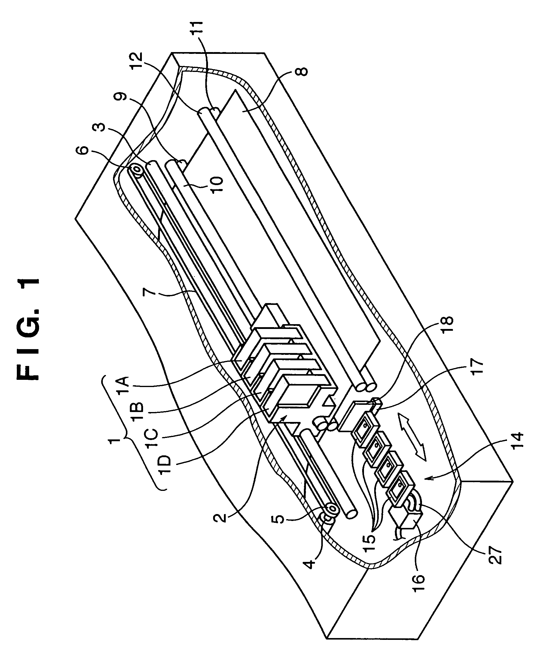
[0119]The first embodiment in which the present invention is applied to the inkjet printing apparatus having the above arrangement will be described below.

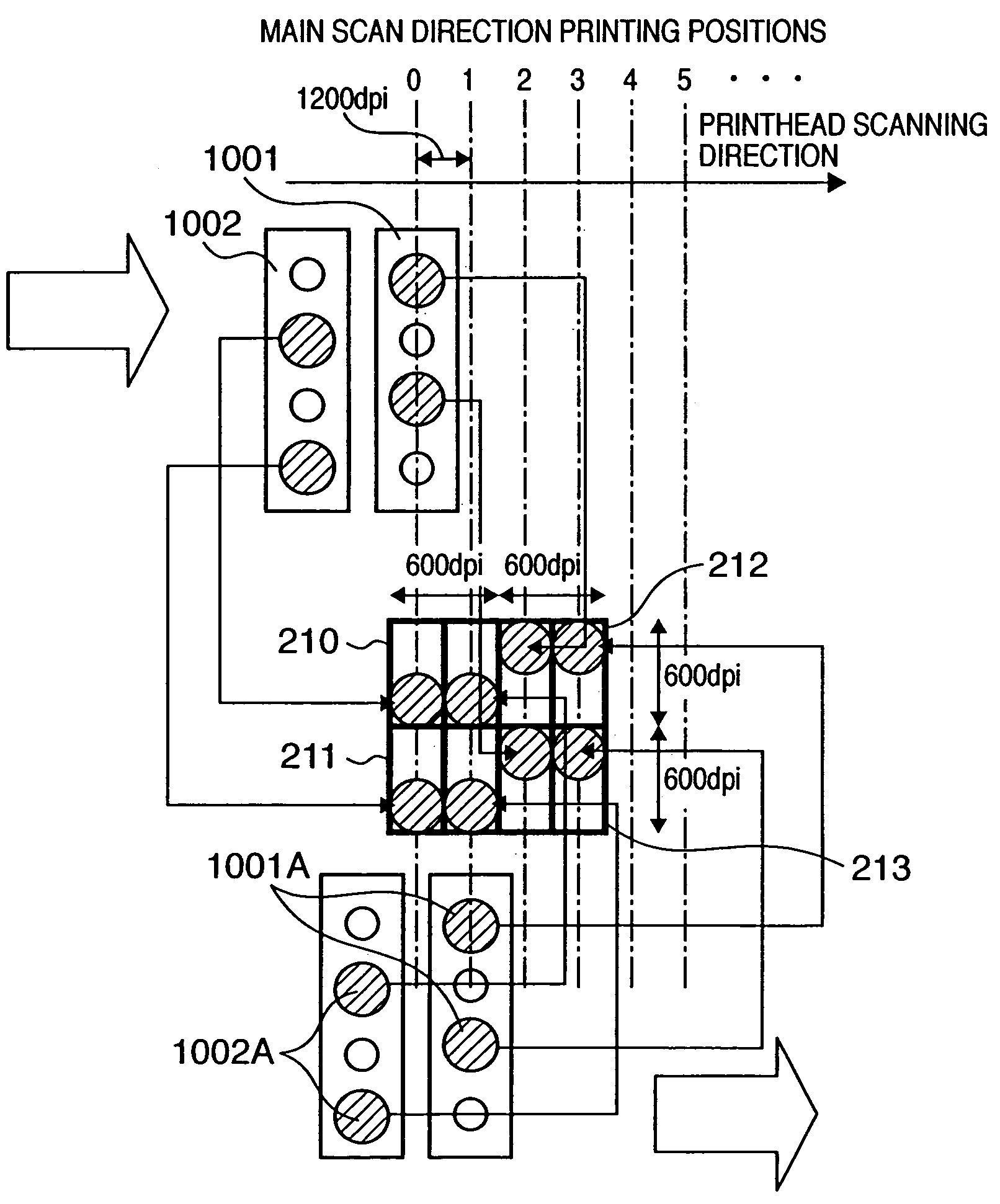
[0120]The first embodiment includes a printhead having two types of discharge orifice groups (large and small nozzles) different in discharge amount, and has a printing mode in which printing is performed by using only one nozzle group during the same main scan, and a printing mode in which printing is performed by driving the two types of nozzle groups at different timings during the same main scan.

[0121]That is, this embodiment is an inkjet printing apparatus which includes at least a first nozzle group used to print dots having a first density, and a second nozzle group used to print dots having a second density, and has a first printing mode in which only one of the first and second nozzle groups is used during printing of one scan, and a second printing mode in which the first and second nozzle groups are driven at different ...

second embodiment

[0173]The second embodiment of the present invention will be described below. The second embodiment also relates to printing position adjustment in an inkjet printing apparatusimilar to that of the first embodiment. In the following description, an explanation of the same portions as in the first embodiment will be omitted, and only the characteristic features of this embodiment will be explained.

[0174]In the first embodiment, printing position adjustment performed for two nozzle rows during scan (one scan) in one direction is described. In this embodiment, printing position adjustment performed when two-way printing is performed will be explained. As in the first embodiment, assume that the size of a target pixel is 600 dpi, and driving timings can be set at a pitch of 1,200 dpi.

[0175]That is, the second embodiment is characterized in that when printing is performed by scanning a printhead forward and backward, set values of the forward and backward relative printing positions of t...


PUM


Abstract

An inkjet printing apparatus prints by scanning an inkjet printhead for discharging ink and a printing medium relative to each other. The printhead includes a first nozzle group used to print a dot having a first density, and a second nozzle group used to print a dot having a second density. The inkjet printing apparatus has a first printing mode in which only one of the first and second nozzle groups is used during one printing scan, and a second printing mode in which the first and second nozzle groups are driven at different timings during one printing scan. In this inkjet printing apparatus, a pattern for adjusting the relative printing positions of the nozzle rows in the first printing mode is printed. From this pattern, set values of relative printing positions in the first printing mode are specified. On the basis of the specified set values, set values of the relative printing positions of the nozzle rows in the second printing mode are determined.

Description

FIELD OF THE INVENTION[0001]The present invention relates to an inkjet printing apparatus and a printing position setting method of the apparatus and, more particularly, to the adjustment of relative printing positions of nozzle rows in an inkjet printing apparatus which prints by using a printhead having a plurality of nozzles for printing dots (dot means the smallest unit which constitutes a pixel) different in density, and also having a plurality of nozzle rows.[0002]The present invention is applicable to all apparatuses using printing media such as paper, cloth, leather, nonwoven fabric, OHP sheets, and metals. Practical examples are business machines such as printing apparatus, copying machines, and facsimile apparatuses, and industrial production apparatuses.BACKGROUND OF THE INVENTION[0003]As information output apparatuses for, e.g., wordprocessors, personal computers, and facsimile apparatuses, printing apparatus which print desired information such as characters and images ...

Claims


Application Information

Patent Timeline
IPC IPC(8): B41J2/15B41J2/05B41J2/205B41J2/21B41J19/20
CPCB41J2/04551B41J2/04563B41J2/04573B41J2/0458B41J2/04581B41J2/15B41J2/2056B41J2/2125B41J19/202
Inventor CHIKUMA, TOSHIYUKINAITO, HISATSUGUKANDA, HIDEHIKO
Owner CANON KK
Why Eureka
Try Eureka