Dual mirror mounting assembly

a mounting assembly and mirror technology, applied in the direction of machine supports, maintaining head carrier alignment, instruments, etc., can solve the problems of increased vibration of the mirror, prone to vibration, and the second mounting assembly of the cross-view mirror can still be subject to vibration, so as to achieve the effect of avoiding vibration and mounting problems

Active Publication Date: 2007-08-07
ROSCO
View PDF19 Cites 23 Cited by
  • Summary
  • Abstract
  • Description
  • Claims
  • Application Information

AI Technical Summary

Benefits of technology

[0012]Accordingly, it is an object of the present invention to provide an improved mounting assembly wherein a single mirror mount assembly is particularly useful for mounting thereon and firmly holding both the rear and cross view mirrors which alleviates the vibration and mounting problems associated with the prior art devices.
[0013]Pursuant to this object and others which will become apparent hereafter, one implementation of the present invention provides a mirror mounting bracket in which the mounting bracket has at least two arms that are mounted directly to the vehicle bulkhead. This mounting of the bracket arms to the bulkhead avoids the vibrations created in the body panel. The mounting bracket also does not require any holes to be drilled in the exterior of the body panel. These two arms of the bracket are configured at one end to be mountable at the engine bay at, preferably, the same points at which the fender is fastened to the vehicle bulkhead or frame.
[0016]In either case, the pivot pin is anchored to the vehicle frame, and not to the sheet metal vehicle body, so the mirrors are less subject to vibration than in conventional installations. Also, the mounting bracket can be located such that the mirror arms can be shorter than in conventional installations, and do not have to project outwardly as far as in such installations, the are less prone to vibration for these reasons as well.

Problems solved by technology

This type of mounting of course requires elongated mounting arms which are often prone to vibration.
Furthermore, in the prior art mirrors, the mounting arms are generally fixed to the body panels of the vehicle which also vibrate during operation of the vehicle and thus leads to an even greater vibration of the mirror.
However, the second mounting assembly for the cross view mirror can still be subject to vibration for the reasons stated above.
These holes, especially those made in the fender of the vehicle in the vicinity of the wheel well, expose the bare metal of the body panel to moisture which leads to rust and corrosion developing in the area of the mounting hole.
Due to the relatively thin metal used in constructing motor vehicles, in a very short period of time the area around the mounting hole becomes rusted and is no longer structurally sound and thus is no longer able to adequately hold the mounting assembly.
This results in having to either repair the body panel and remount the mounting assembly or move the mounting assembly to another location which entails drilling new holes in the body panel.
This in turn leaves the body panel in the area of the previously-drilled holes to further deteriorate.
The problem with this type of device is that it is easily removed and is thus subject to theft.
Furthermore, since the mounting arms are mounted to the body panel there is also the problem of vibrations being amplified by the mounting arms.

Method used


Image

  • Dual mirror mounting assembly
  • Dual mirror mounting assembly
  • Dual mirror mounting assembly

Examples


Embodiment Construction

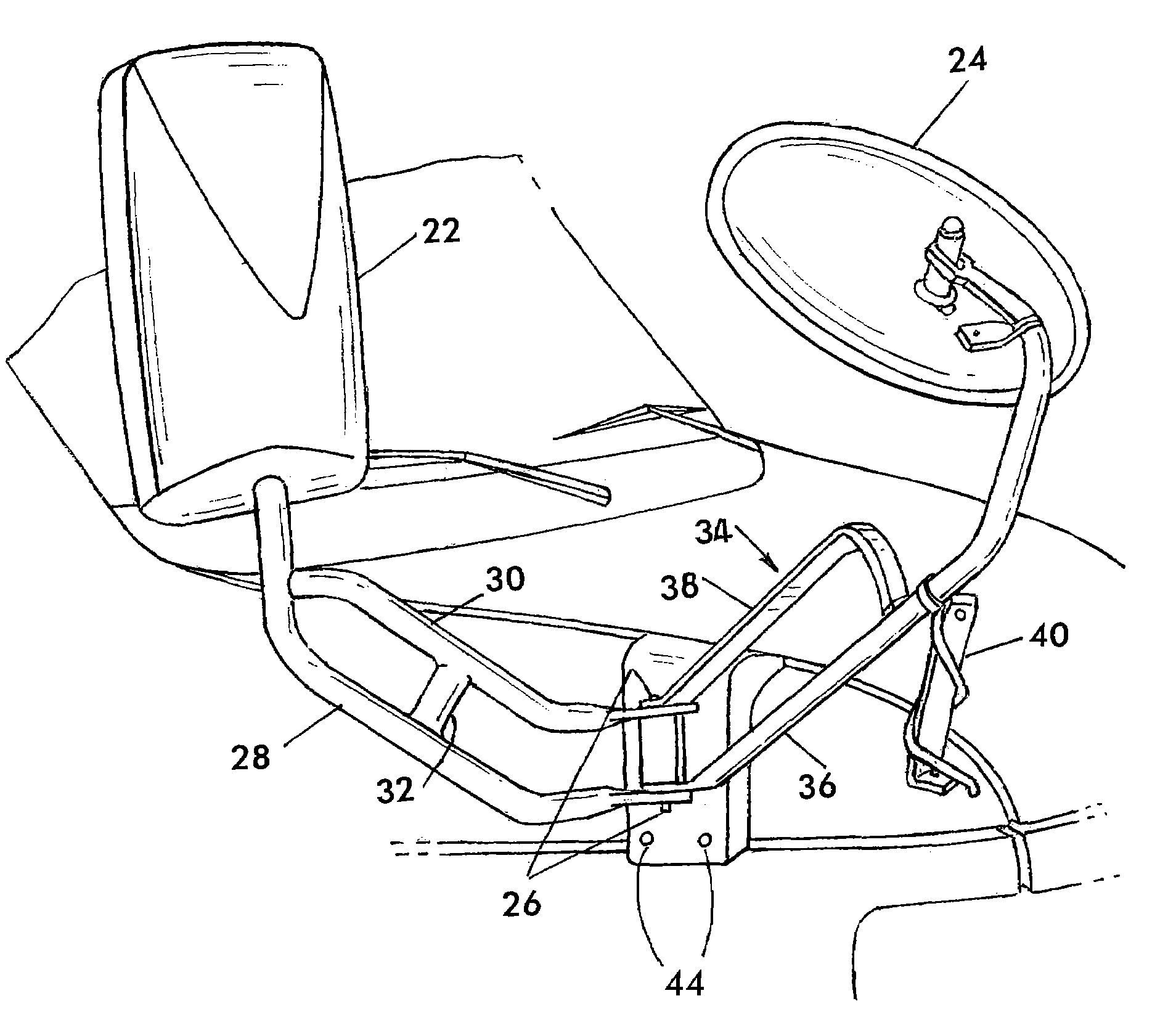
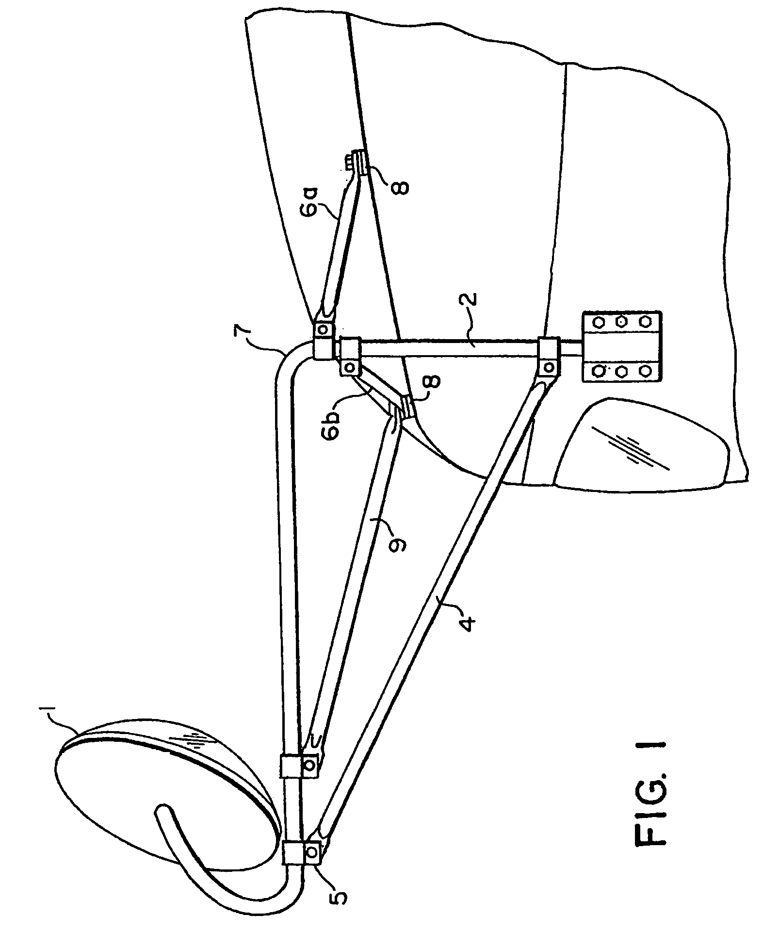
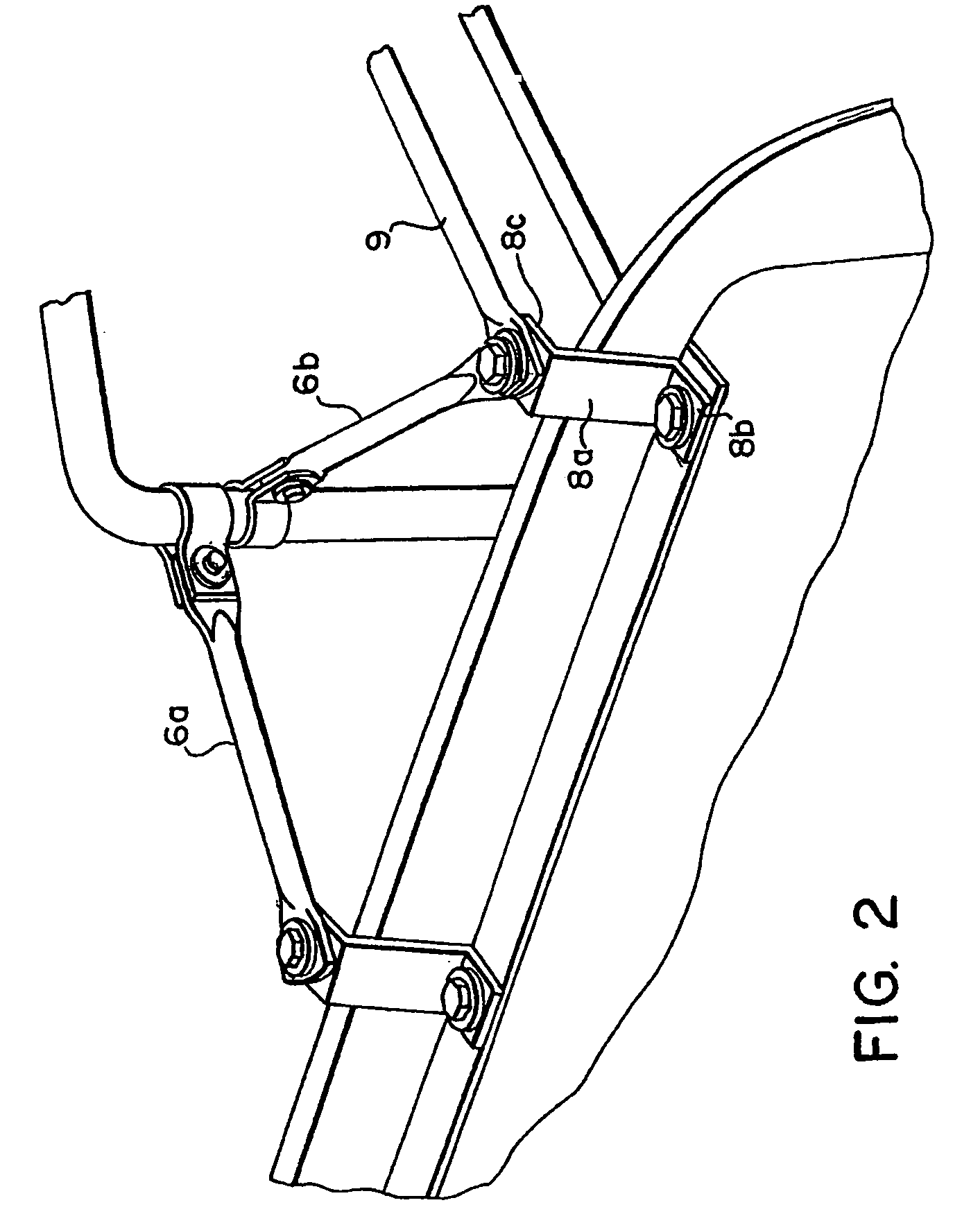
[0028]As can be seen in FIG. 1, a first embodiment of the inventive mirror mounting assembly has a mirror element 1 mounted to one end of a main support member 2. In this embodiment, the main support member 2 has a substantially L-shape. The mirror 1 is attached to the free end of the long leg of the L-shaped support member 2. The end of the short leg of the support member 2 is attachable to the vehicle. This end of the support member 2 can be attached either directly to the vehicle panel as shown in FIG. 1, or can be clipped around the edge of the wheel well by a bracket or clip 3 attached to the end of the support member 2 (see FIG. 5). A support arm 4 extends between the free end of the long leg of the L-shaped support member 2 and the end of the short leg of the L-shaped support member 2. The support arm 4 can be attached to the support member 2 in any one of a variety of ways, including clamping 5 or welding. Two additional support arms 6a, 6b extend from the short leg of the L...


PUM

PropertyMeasurementUnit
angleaaaaaaaaaa
lengthsaaaaaaaaaa
widths widthaaaaaaaaaa

Abstract

A mirror mounting assembly for mounting a mirror on a vehicle bulkhead. The assembly includes a generally Z-shaped mirror mounting bracket configured for attachment to a structural portion of the vehicle inside an engine bay of the vehicle, and a support member connected to the mounting bracket. The mounting bracket includes a first flange and a second flange extending laterally in opposite directions from opposed edges of a connecting web. The first flange has two through-holes sized and positioned for connection to the structural portion inside engine bay by existing body panel mounting screws. The second flange and the connecting web are sized and configured so that the second flange extends out of the engine bay upon installation of the bracket. The support member carries a pivot element sized and configured to pivotally support a first support arm assembly for a rear view mirror unit and a second support arm assembly for a cross view mirror unit.

Description

CROSS-REFERENCE TO RELATED APPLICATION[0001]This application is a Continuation-in-Part of U.S. application Ser. No. 10 / 737,238, filed Dec. 15, 2003 now U.S. Pat. No. 7,055,973 in the name of Benjamin Englander and entitled MIRROR MOUNTING ASSEMBLY, the contents of which are incorporated herein by reference.BACKGROUND OF THE INVENTION [0002]1. Field of the Invention[0003]The present invention relates to a mounting assembly for mounting a mirror to a motor vehicle, and more particularly, in one aspect, to a low-vibration mounting assembly for both a rear view and separate cross-view mirror.[0004]2. Description of the Prior Art[0005]Side view mirrors which are used on buses and trucks are well known in the art as evidenced by U.S. Pat. Nos. 3,395,883, 4,368,868, 4,500,063, 4,512,634, 5,106,049 and 5,316,257, the contents of which are incorporated by reference herein.[0006]Particularly in the case of school busses, it is desirable for mirrors to be mounted so that the driver can see bot...

Claims


Application Information

Patent Timeline
Patent Type & Authority Patents(United States)
IPC IPC(8): G02B5/10B60R1/06G02B7/182G11B21/02G11B5/48G11B5/55G11B5/56G11B5/596G11B7/085G11B21/21
CPCB60R1/0605G02B7/182G11B5/4826G11B5/5552G11B5/56G11B5/596
Inventor ENGLANDER, BENJAMIN
Owner ROSCO
Why Eureka
Try Eureka