Vibration source driving device

a driving device and vibration source technology, applied in the direction of mechanical vibration separation, tactile signalling system, instruments, etc., can solve the problems of complex circuit configuration and user's feeling of wrongness

Inactive Publication Date: 2007-08-07
YAMAHA CORP
View PDF35 Cites 89 Cited by
  • Summary
  • Abstract
  • Description
  • Claims
  • Application Information

AI Technical Summary

Benefits of technology

[0010]In the aforementioned configuration, the low-frequency components are extracted from the musical tone signals output from the sound source, so that the vibration source is driven based on the low-frequency components of the musical tone signals. Therefore, in the case of the portable telephone that is set to allow incoming call notification by both the sound (i.e., melody of the musical tune) and vibration, the vibration occurs in synchronization with the rhythm of the musical tune that is output as the sound. Hence, it is possible to obtain an effect that the user is able to enjoy it without having a feeling of wrongness.
[0012]In the aforementioned configuration, driving the vibration source responsive to the low-frequency components of the musical tone signals output from the sound source is realized by the control means that performs on / off controls on the switch means, provided between the sound source and amplifier 22, based on the timing signal representing the output period of the rhythm signal, which represents the rhythm sound within the musical tone signals output from the sound source 10. Therefore, in the case of the portable telephone that is set to allow incoming call notification by both the sound (i.e., melody of the musical tune) and vibration, the vibration occurs in synchronization with the rhythm of the musical tune that is output as the sound. Hence, it is possible to obtain an effect that the user is able to enjoy it without having a feeling of wrongness.
[0017]In the present invention having the aforementioned configuration, the vibration speaker for generating sound and vibration in different frequency bands is used as the vibration source, which is driven by signals transmitted through the variable filter that can change frequency characteristics of the musical tone signals output from the sound source by the setting input. Therefore, when the vibration speaker is used as the vibration source, that is, the means for actualizing the vibration function on the portable telephone that allows generation of sound (acoustic sound or speech) only, generation of vibration only, or simultaneous generation of sound and vibration, it can be driven by the normal speaker drive amplifier without using the complicated circuit configuration. When the portable telephone is set to allow notification of an incoming call by both sound (melody of the tune) and vibration, the vibration is generated in synchronization with the rhythm of the tune that is output as the sound; therefore, it is possible to obtain an effect that the user can enjoy it without having a feeling of wrongness.
[0019]When the portable telephone is set to allow notification of an incoming call by both sound (melody of the tune) and vibration, it is possible to generate vibrations having different characteristics in response to the vibration signals generated by the sound source. Hence, it is possible to obtain an effect that the user can enjoy it without having a feeling of wrongness.
[0020]In the present invention, the signals that is extracted by eliminating low-frequency components from the musical tone signals output from the sound source are added to the vibration signals that are synchronized with the rhythm within the musical tone signals output from the sound source, so that the vibration speaker as the vibration source is driven by the addition output. Therefore, when the vibration speaker is used as the vibration source, that is, the means for actualizing the vibration function on the portable telephone, it is possible to obtain an effect that the vibration source can be driven by the normal speaker drive amplifier without using the complicated circuit configuration.
[0021]When the portable telephone is set to allow notification of an incoming call by both sound (melody of the tune) and vibration, the vibration is generated in synchronization with the rhythm of the tune that is output as the sound. Therefore, it is possible to obtain an effect that the user can enjoy it without having a feeling of wrongness.

Problems solved by technology

However, the sound such as the melody of the musical tune does not have correlation to the vibration; therefore, when the conventional telephone is used with the setting for allowing incoming call notification by simultaneously generating sound and vibration, there is a problem in that the user of the portable telephone may have a feeling of wrongness.
For this reason, there is a problem that the circuit configuration should be complicated.

Method used


Image

  • Vibration source driving device
  • Vibration source driving device
  • Vibration source driving device

Examples


first embodiment

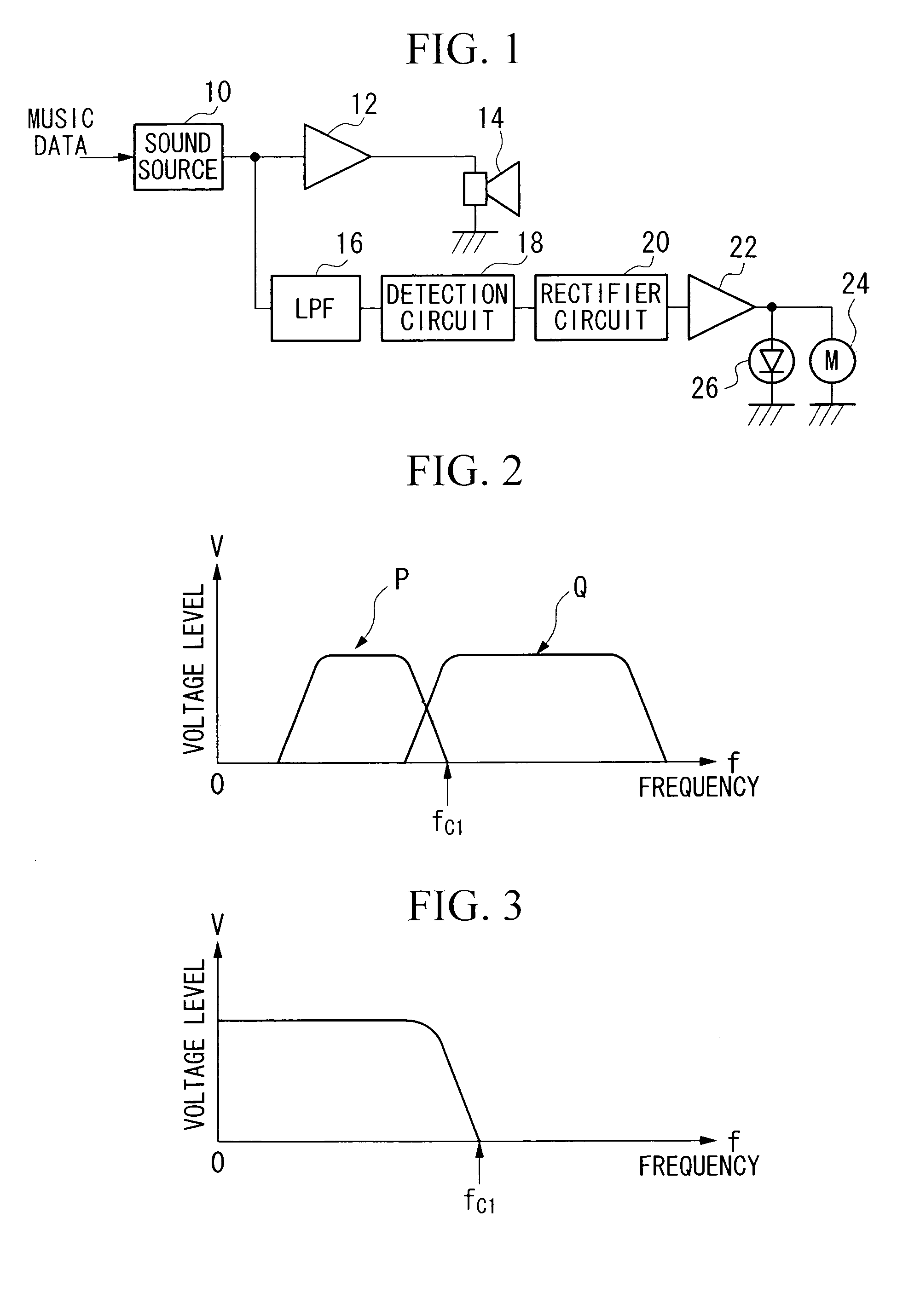
[0045]FIG. 1 shows the configuration of the vibration source driving device in accordance with the first embodiment of the present invention. In this figure, the vibration source driving device of the first embodiment comprises a sound source 10 for generating musical tone signals, a DC motor 24 as a vibration source for generating vibration, a low-pass filter (LPF) 16 as a signal extraction means for extracting low-frequency components from the musical tone signals output from the sound source 10, a detection circuit 18 for performing detection on the output signal of the low-pass filter 16, a rectifier circuit 20 for rectifying the detection output of the detection circuit 18, and an amplifier 22 as a drive means for driving the vibration source based on the low-frequency components of the musical tone signals extracted by the low-pass filter 16.

[0046]12 designates an amplifier for amplifying musical tone signals output from the sound source 10; 14 designates a speaker that is dri...

second embodiment

[0053]Next, FIG. 5 shows the configuration of the vibration source driving device in accordance with the second embodiment of the present invention. The vibration source driving device of the second embodiment differs from the vibration source driving device of the first embodiment in configuration in that there are provided a comparator 30, a reference voltage generation circuit 32, a transistor 34 as a switching element to be turned on or off by the output of the comparator 30, and a resistor 36, at the output side of the rectifier circuit 20 shown in FIG. 1, wherein a power source Vcc is connected to one ends of the DC motor 24 and photodiode 26 via the resistor 36 and the transistor 34. Other parts of the configuration of the second embodiment are identical to the vibration source driving device of the first embodiment; therefore, the same parts are designated by the same reference numerals; hence, the duplicate description will be omitted.

[0054]In the aforementioned configurati...

third embodiment

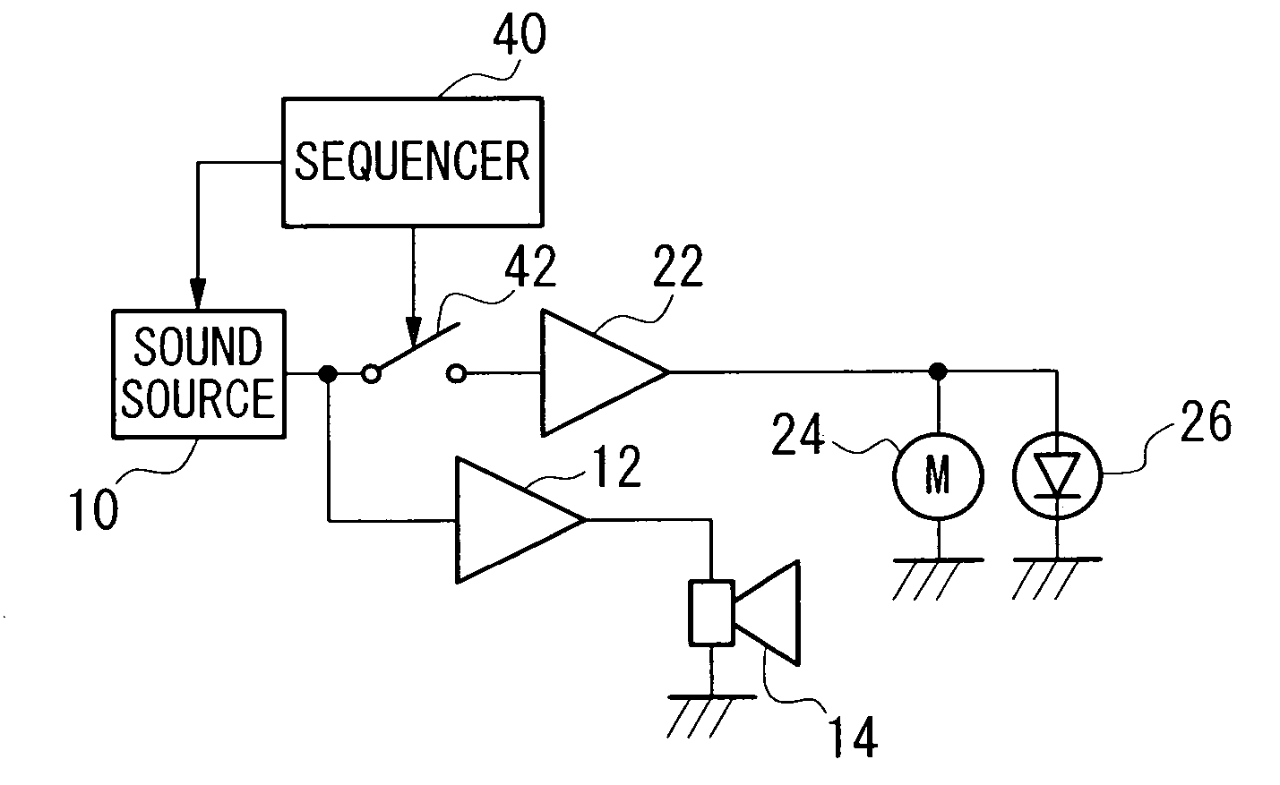
[0059]Next, FIG. 7 shows the configuration of the vibration source driving device in accordance with the third embodiment of the present invention. The vibration source driving device of the third embodiment differs from the vibration source driving device of the first embodiment in configuration in that driving the DC motor as the vibration source by low-frequency components of musical tone signals output from the sound source 10 in the configuration of the vibration source driving device of the first embodiment shown in FIG. 1 is achieved by a sequencer 40 that controls a switch 42, which is provided between the sound source and the amplifier 22, to be turned on or off on the basis of timing signals representative of periods for outputting rhythm signals representing rhythm sounds within musical tone signals output from the sound source 10. The other parts of the configuration of the third embodiment are identical to the vibration source driving device of the first embodiment; the...


PUM


Abstract

A vibration source driving device that realizes various vibration functions on portable telephones. The vibration source driving device includes a sound source for generating musical tone signals in response to music data. A vibration source to generate vibration, a driver to drive the vibration and a control circuit are further included such that the vibration source may be driven in synchronization with the rhythm signal within the music data.

Description

[0001]This application is a continuation application of application Ser. No. 10 / 110,871, filed Apr. 18, 2002, which is a section 371 application of PCT / JP00 / 07378, filed Oct. 23, 2000.TECHNICAL FIELD[0002]The present invention relates to vibration source driving devices, and particularly to vibration source driving devices that realize vibration functions on portable telephones.BACKGROUND ART[0003]The conventional portable telephones are each constituted to allow the setting for a vibrator to be driven at an incoming call mode in order to notify an incoming call by causing vibration other than a melody and the like. Generally, this vibrator has a DC motor in which a weight is attached in a deflected manner to a rotation shaft of a rotor; therefore, by driving it to rotate, vibration is generated.[0004]By the way, the aforementioned portable telephones can be each set to notify users with incoming calls with both sound and vibration by driving the vibrator simultaneously with generat...

Claims


Application Information

Patent Timeline
Patent Type & Authority Patents(United States)
IPC IPC(8): G10H1/00B06B1/02H04R1/00B06B1/04G08B6/00H04M1/00
CPCB06B1/0207B06B1/0215B06B1/045G08B6/00B06B2201/52B06B2201/53B06B2201/55B06B2201/70B06B1/04
Inventor NORO, MASAOTANAKA, TAKAHIROTOBA, NOBUKAZUYAMAKI, KIYOSHI
Owner YAMAHA CORP
Why Eureka
Try Eureka