Enhanced waveguide metrology gauge collimator

a collimator and waveguide technology, applied in the field ofmetrology gauges, can solve the problems of compromising the required signal level, affecting the accuracy of metrology gauges, so as to achieve high quality wavefront flatness, low cost and convenient opto-mechanical alignment and manufacture.

a collimator and waveguide technology, applied in the field ofmetrology gauges, can solve the problems of compromising the required signal level, affecting the accuracy of metrology gauges, so as to achieve high quality wavefront flatness, low cost and convenient opto-mechanical alignment and manufacture.

US7254290B1Active Publication Date: 2007-08-07LOCKHEED MARTIN CORP

Image

  • Enhanced waveguide metrology gauge collimator
  • Enhanced waveguide metrology gauge collimator
  • Enhanced waveguide metrology gauge collimator

Examples


Embodiment Construction

[0044]The present invention provides an enhanced collimator for use with an improved precision metrology gauge. Additionally, the present invention provides for the achievement of a stable high measurement accuracy within a laboratory or measurement environment of diverse temperature gradients, without requiring perfect alignment of the collimator and / or retroreflecting element.

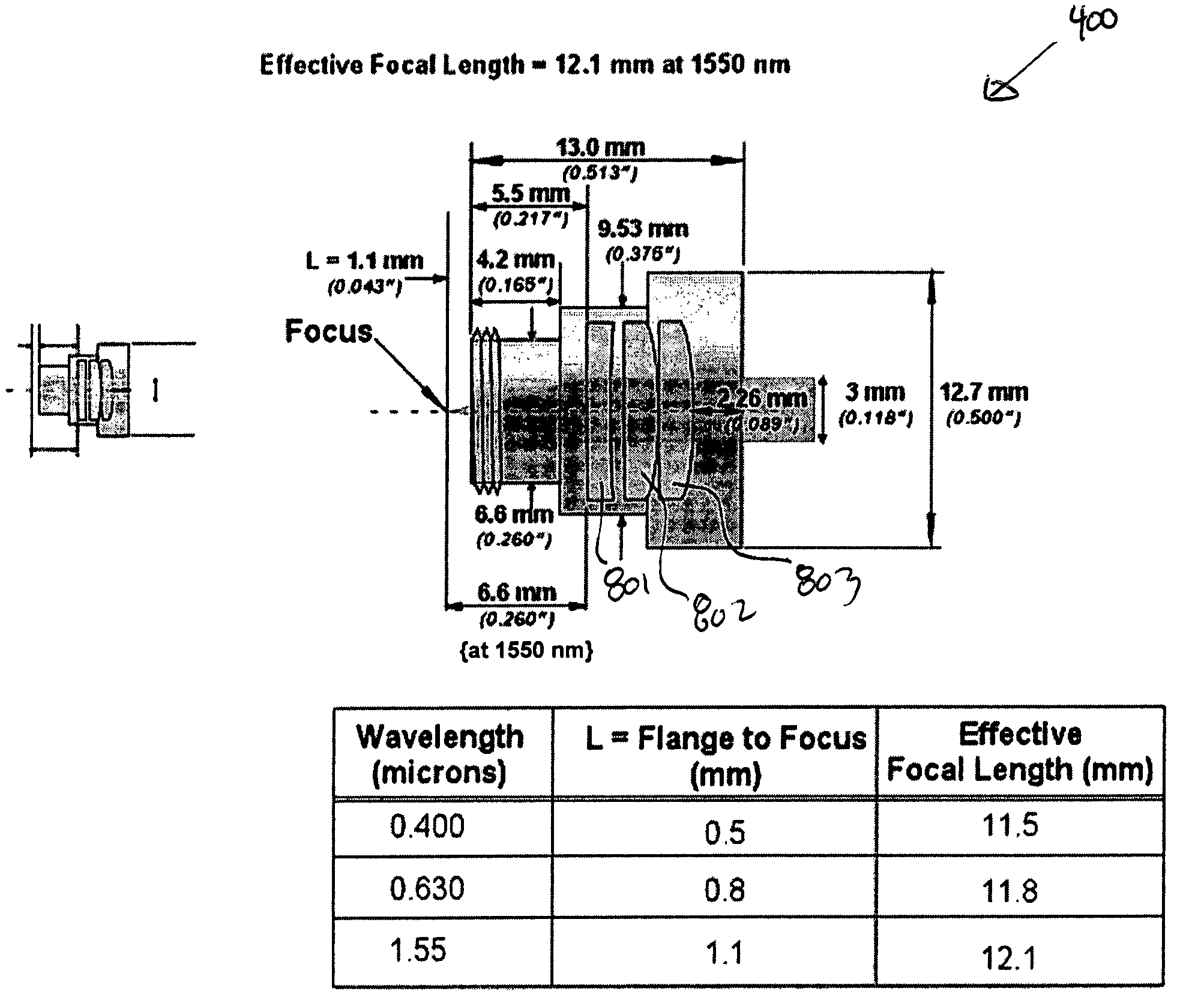
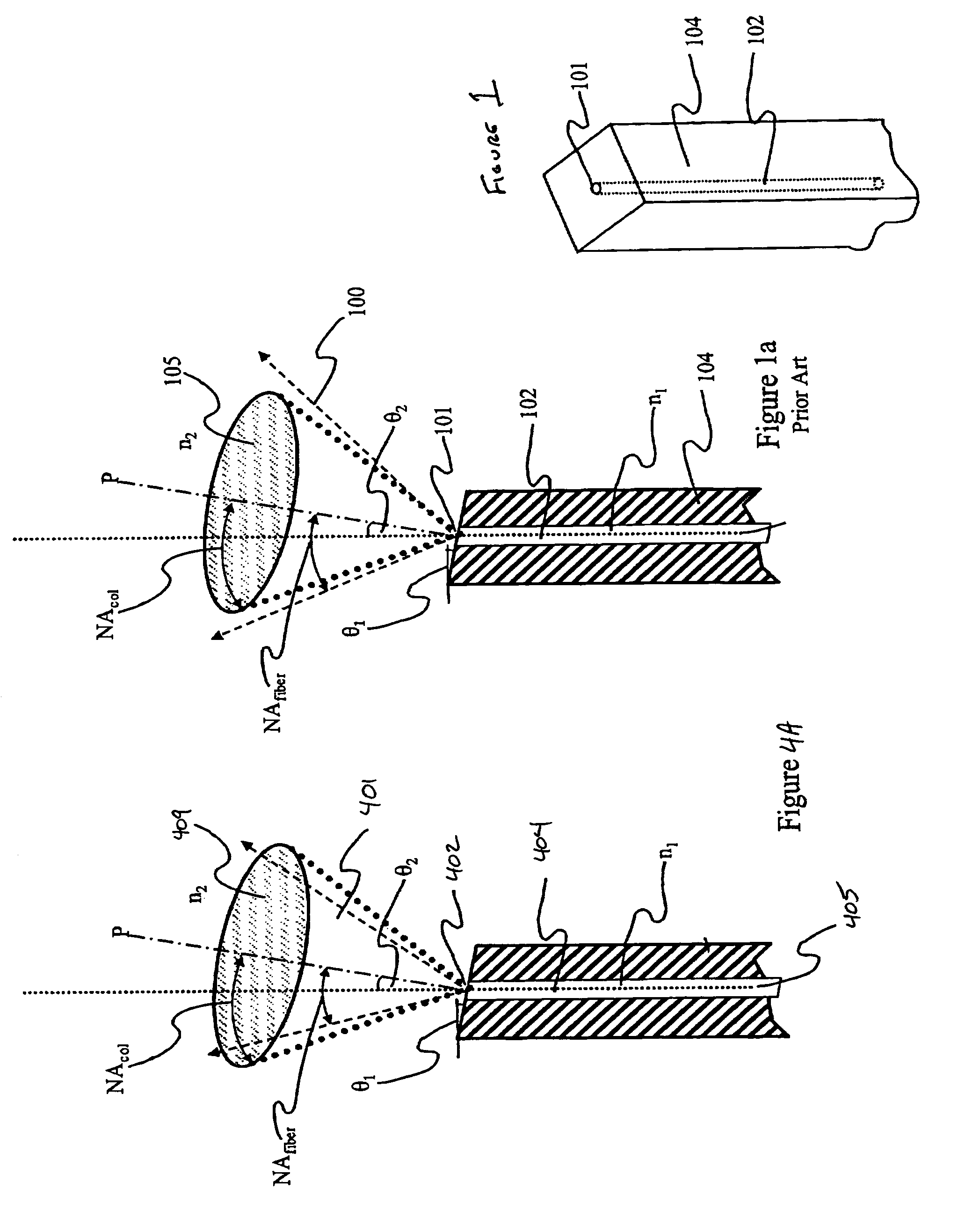
[0045]FIGS. 4 and 4A depict the free-space optically-coupled collimator for the efficient bidirectional transmission of an optical metrology beam emanating from a waveguide aperture of a waveguide optical transmission element, according to one arrangement of the present invention. The focus of the collimator is set at the waveguide aperture of the waveguide optical transmission element, the optical axis of the collimator aligns with the optical metrology beam as it exits the waveguide aperture of the waveguide optical transmission element, and the numeric aperture of the collimator is equal to or larger than ...


PUM


Abstract

A free-space optically-coupled collimator for the efficient bidirectional transmission of an optical metrology beam emanating from a waveguide aperture of a waveguide optical transmission element, all contained in an isothermal nested enclosure, with the waveguide element mounted in a stress-free fashion. The focus of the collimator is set at the waveguide aperture of the waveguide optical transmission element, the optical axis of the collimator aligns with the optical metrology beam as it exits the waveguide aperture of the waveguide optical transmission element, and the numeric aperture of the collimator is equal to or larger than the numeric aperture of the optical metrology beam as it exits the waveguide aperture of the waveguide optical transmission element.

Description

[0001]This application claims the benefit of U.S. Provisional Application No. 60 / 569,231, filed May 10, 2004, which is hereby incorporated by reference.STATEMENT AS TO RIGHTS TO INVENTIONS MADE UNDER FEDERALLY SPONSORED RESEARCH OR DEVELOPMENT[0002]Not Applicable.FIELD OF THE INVENTION[0003]The present invention relates generally to metrology gauges, and more particularly relates to the improvement of metrology gauge precision using an enhanced collimator and mount design which utilizes an improved isothermal housing and low-stress waveguide mount.BACKGROUND OF THE INVENTION[0004]U.S. patent application Ser. No. 10 / 051,122 (“Bell”) discloses a conventional robust heterodyne interferometer which incorporates a planar lightwave circuit (“PLC”), for precisely measuring distances. The conventional interferometer typically propagates a measurement optical signal through a single mode optical fiber or waveguide, where the optical signal exits the optical fiber or waveguide via an exit ape...

Claims


Application Information

Patent Timeline
07 Aug 2007
Publication
US7254290B1
IPC
G02B6/12; G01B9/02; G01J5/08
CPC
G01J1/02; G01J1/0252; G01J1/0271; G01J1/04; G01J1/0403; G01J1/0411; G01J1/0425; G02B6/32
Inventors
SOMERSTEIN, STEPHEN F.; MAMMINI, PAUL V.