
Receiver system for decoding data embedded in an electromagnetic signal

a technology of electromagnetic signals and receivers, applied in the direction of transmission, automatic scanning with station selection, telephonic communication, etc., can solve the problems of untrustworthy announcements, repetitive and irritating, unacceptable listeners,

Active Publication Date: 2007-08-07
HARMAN BECKER AUTOMOTIVE SYST
View PDF17 Cites 15 Cited by
  • Summary
  • Abstract
  • Description
  • Claims
  • Application Information

AI Technical Summary

Benefits of technology

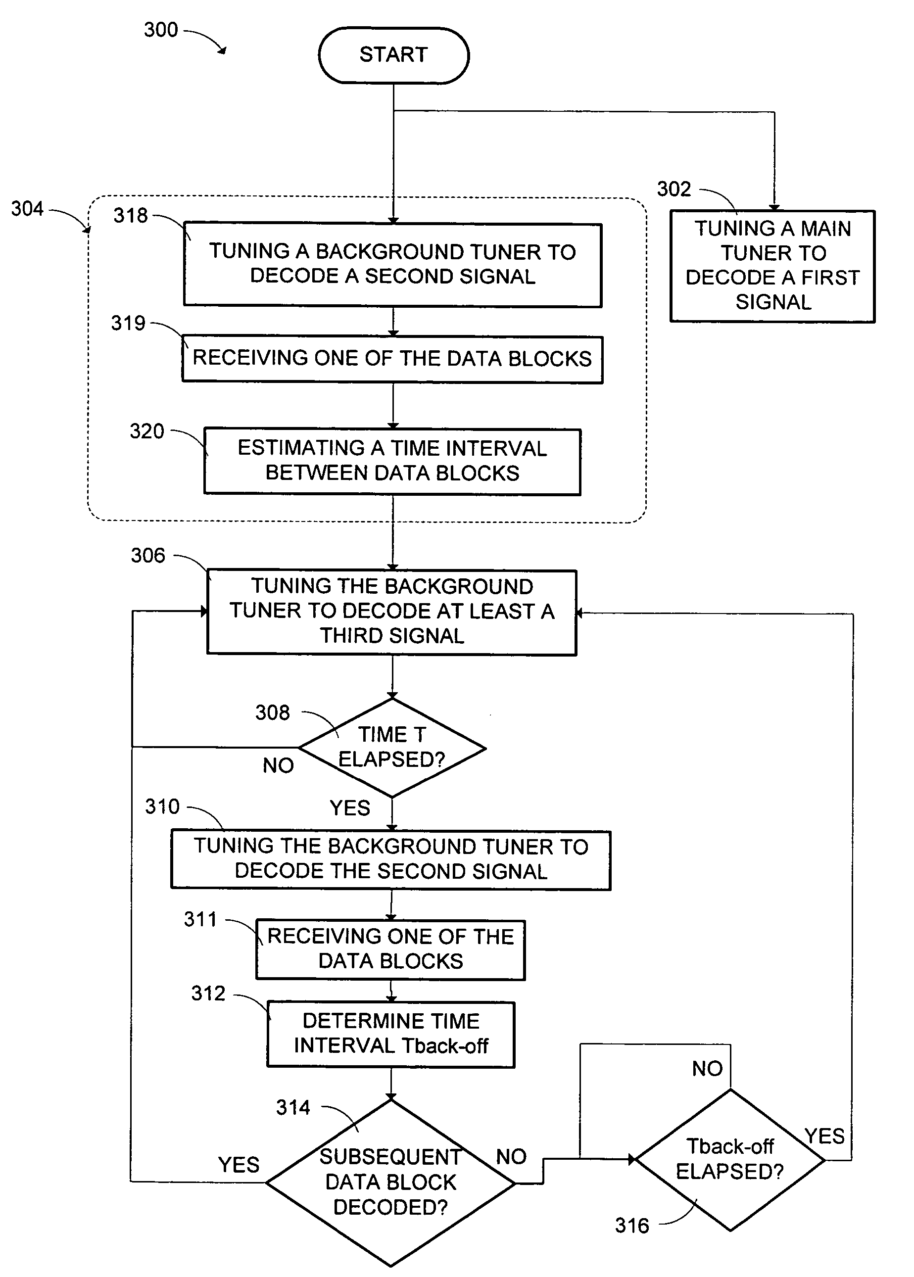
The patent describes a method and receiver system for accurately and efficiently receiving data blocks from signals, such as radio broadcast signals. The method allows the receiver to constantly and simultaneously receive data blocks from multiple signals without impairing the ability of the background tuner to scan for alternative frequencies. The receiver system includes a main tuner, background tuner, and timer to perform the demodulation and decoding functions. The technical effects of this invention include improved accuracy, timeliness, and relevance of information received from signals.

Problems solved by technology

Broadcasters, such as radio broadcasters, cannot respond simply by increasing the number of on-air announcements that are broadcast using traditional delivery modes, because this would be unacceptable to listeners.
Many listeners are concerned that such announcements are untrustworthy, repetitive and irritating unless the information is relevant to them.
However, receivers that include a main tuner and a background tuner cannot use the background tuner to constantly decode the TTI (such a TM data) without impairing the ability of the background tuner to scan the frequency band for alternative frequencies at which signals containing the same data stream (such as a radio program) as contained in the signal received by the main tuner are modulated (the “diversity function” of the background tuner).

Method used


Image

  • Receiver system for decoding data embedded in an electromagnetic signal
  • Receiver system for decoding data embedded in an electromagnetic signal
  • Receiver system for decoding data embedded in an electromagnetic signal

Examples


Embodiment Construction

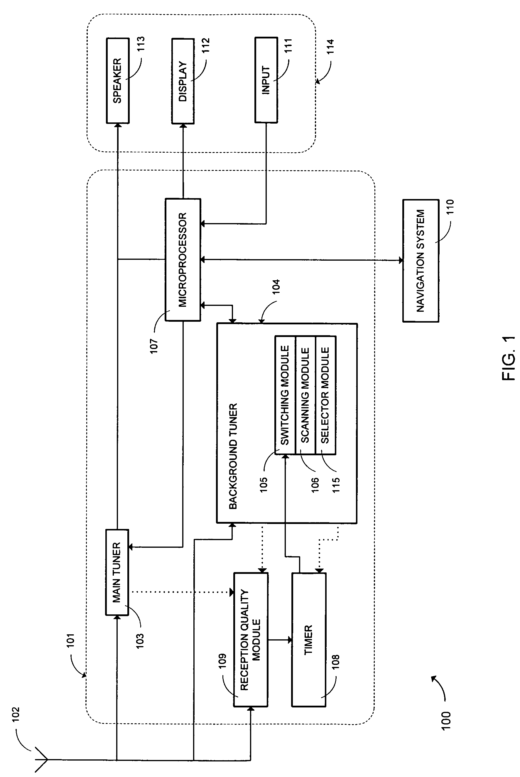
[0021]An example of a receiver system for decoding data embedded in electromagnetic signals, such as radio broadcast signals, is shown in FIG. 1. The receiver system 100 may be used in a variety of environments, including vehicles, and generally includes an input device 102, a receiver 101, and an interface 114. The input device 102 may include an antenna or other device that can detect and communicate electromagnetic signals. These electromagnetic signals may include broadcasted signals, such as radio broadcast signals. A radio broadcast signal generally includes a data stream communicating a program that is transmitted, generally through the air, to a receiver. To create the radio broadcast signal, the data stream is modulated on a carrier wave of a given frequency. Many radio broadcast signals may be simultaneously transmitted because each signal may be modulated at a different frequency or channel.

[0022]The input device 102 generally detects, and communicates to the receiver 101...


PUM


Abstract

A system for decoding data, such as travel and traffic information, configured in data blocks embedded in an electromagnetic signal, such as a broadcasted radio signal, has been developed. The system includes a method and receiver for decoding the data with a background tuner in a manner that does not impair the ability of the background tuner to demodulate other signals. While a main tuner is tuned to demodulate a first electromagnetic signal to produce a data stream, the background tuner is switched to decode the data blocks only when the data blocks are expected to be received. In the remaining time, the background tuner is free to demodulate other signals to support a diversity or other function. If a data block is not received, or not received when expected, the background tuner returns to demodulating one or more other frequencies after a predetermined time interval has elapsed.

Description

PRIORITY CLAIM[0001]This application claims priority under 35 U.S.C. § to European Patent Application No. 03010418.6, filed May 8, 2003. The disclosure of the above application is incorporated herein by reference.BACKGROUND OF THE INVENTION[0002]1. Technical Field[0003]This invention relates to a receiver including two tuners, which decodes digital data contained in electromagnetic signals, such as radio broadcast signals. Further, this invention relates to a method for decoding digital data in such signals.[0004]2. Related Art[0005]Worsening traffic congestion has generated a demand for accurate and timely information on traffic conditions. Broadcasters, such as radio broadcasters, cannot respond simply by increasing the number of on-air announcements that are broadcast using traditional delivery modes, because this would be unacceptable to listeners. Many listeners are concerned that such announcements are untrustworthy, repetitive and irritating unless the information is relevant...

Claims


Application Information

Patent Timeline
Patent Type & Authority Patents(United States)
IPC IPC(8): H04B1/06H03J1/00H03J7/18H04B1/16H04H20/34H04H20/55H04H40/09
CPCH03J1/0083H04H40/09H03J7/186H04H20/34H04H20/55H04H2201/13H04H2201/60
Inventor BENZ, CHRISTOPHKORNER, ANDREASGIERL, STEFAN
Owner HARMAN BECKER AUTOMOTIVE SYST
Learn More