Combination lock

a combination lock and lock technology, applied in the field of locks, can solve the problems of troublesome password reset, number rotors being accidentally rotated, and being very convenient to res

Inactive Publication Date: 2007-08-14
PATH LINE NGS HLDG
View PDF7 Cites 25 Cited by
  • Summary
  • Abstract
  • Description
  • Claims
  • Application Information

AI Technical Summary

Benefits of technology

[0010]Another object of the present invention is to provide a combination lock comprising a password reset unit which allows a user to reset a password of the combination lock on a lock body thereof without needing to disassemble the lock body. In other words, the password reset unit allows maximum convenience of resetting the password while substantially preventing accidental resetting of the password.
[0011]Another object of the present invention is to provide a combination lock which does not involve complicated mechanical structure so as to minimize the manufacturing cost as well as the ultimate selling price of the present invention.

Problems solved by technology

A main disadvantage of this kind of conventional combination lock is that the password reset button is positioned on the lock body so that it may be accidentally actuated.
In such a scenario, if the user does not notice of the actuation of the password reset button, the number rotors may be accidentally rotated when the password reset button is unknowingly actuated.
A main disadvantage of this kind of combination lock is that reset of password is troublesome and very convenient, though substantially resolving the above-mentioned disadvantage of accidental resetting of passwords.

Method used


Image

  • Combination lock
  • Combination lock
  • Combination lock

Examples


Embodiment Construction

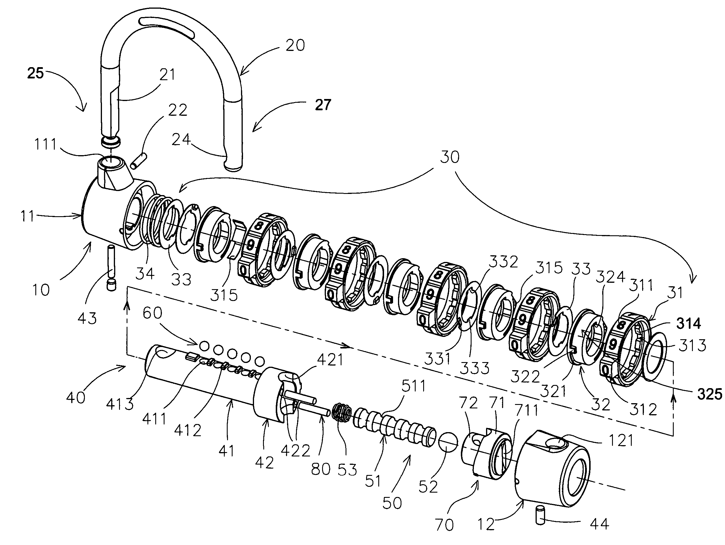
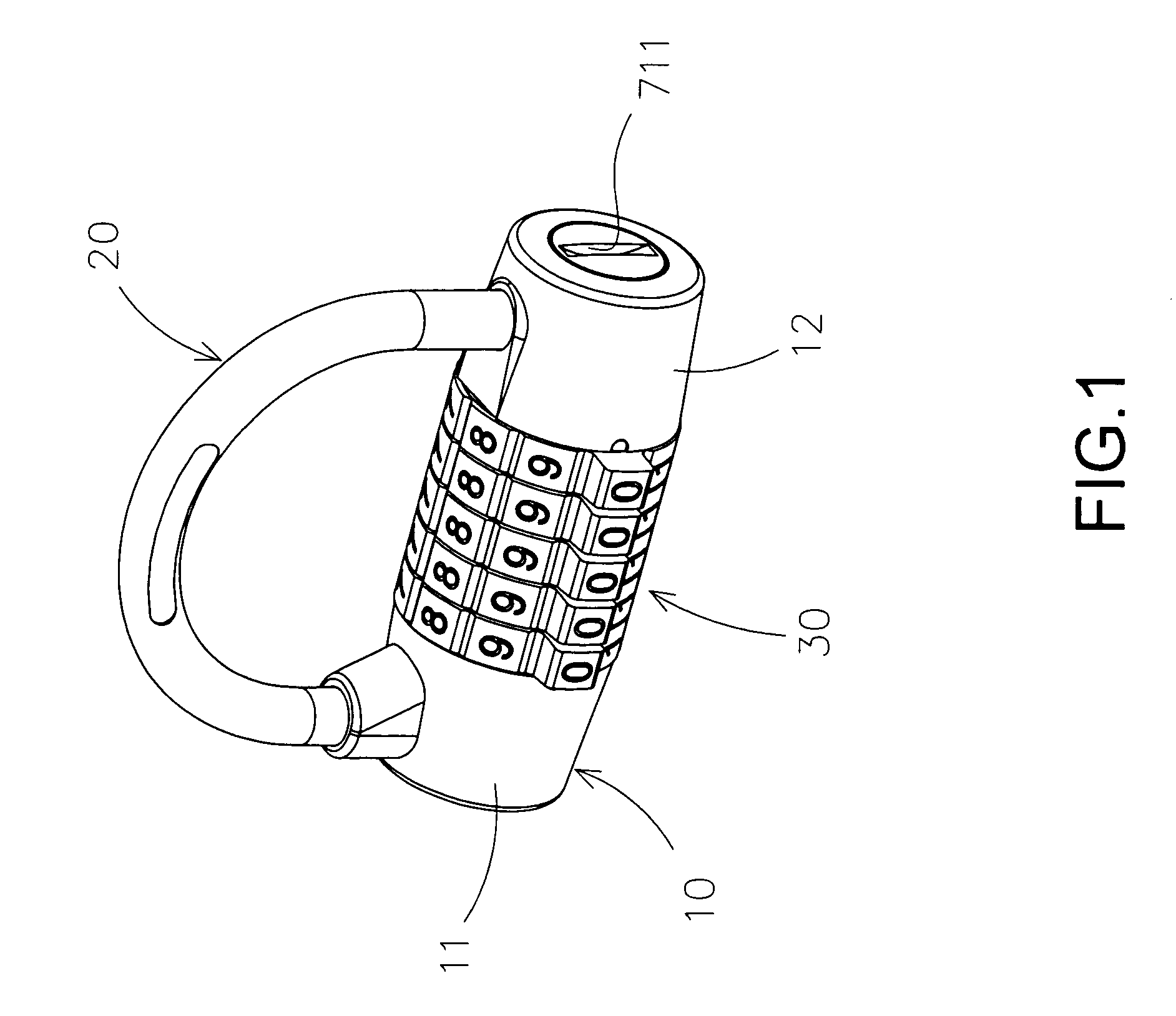
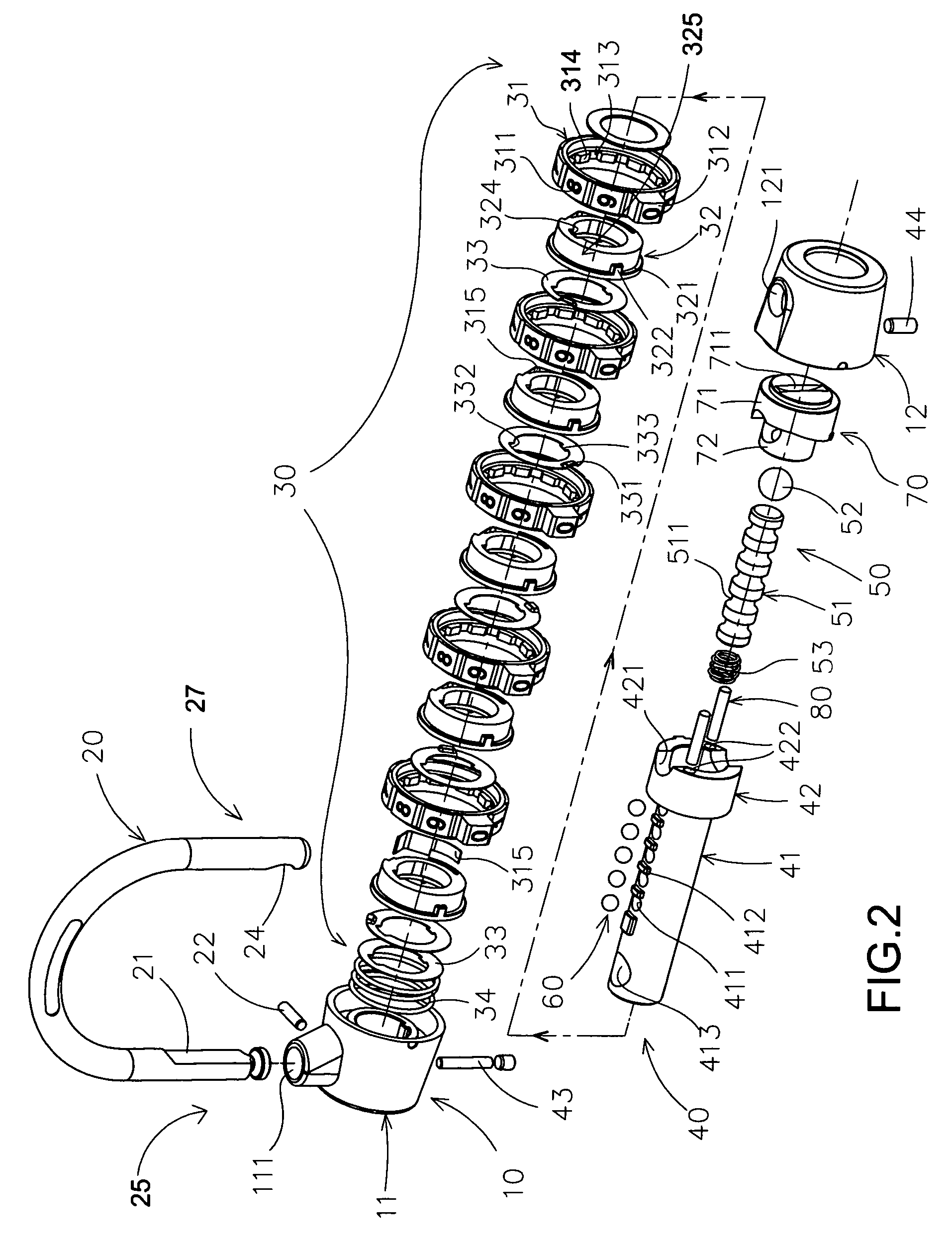
[0024]Referring to FIG. 1, FIG. 2, FIG. 3A and FIG. 3B of the drawings, a combination lock according to a preferred embodiment of the present invention is illustrated. According to the preferred embodiment of the present invention, the combination lock comprises a lock body 10, a locking latch 20, a numerical actuation unit 30, and a password reset unit.

[0025]The lock body 10 has a first latch opening 111 and a second latch opening 121 spacedly formed on the lock body 10 to support the locking latch 20, the numerical actuation unit 30 and the password reset unit.

[0026]The locking latch 20 has a coupling end portion 25 slidably mounted at the first latch opening 111 and a detachable end portion 27 detachably engaged at the second latch opening 121.

[0027]The numerical actuation unit 30 comprises a lock releasing device 40 slidably supported by the lock body 10 to lock up the detachable end portion 27 of the locking latch 20 at the second latch opening 121, a plurality of locking rings...


PUM


Abstract

A combination lock includes a lock body, a locking latch, a numerical actuation unit including a plurality of number rotors and a plurality of locking rings, and a password reset unit. The password reset unit includes a reset driver slidably extended at the lock body to couple with the locking rings, wherein when the reset driver is moved to drive the locking rings to slidably disengage with number rotors, the number rotors are free to rotate on the lock body to reset a new number-combination, such that when the reset driver is released that the locking rings are slidably returned back within the number rotors, the detachable end of the locking latch is unlocked once the number rotors are rotated at the new number-combination.

Description

BACKGROUND OF THE PRESENT INVENTION[0001]1. Field of Invention[0002]The present invention relates to a lock, and more particularly to a combination lock which comprises a password reset unit received in a lock body for preventing it from being accidentally actuated.[0003]2. Description of Related Arts[0004]Locks have been widely used for a wide variety of purposes. For example, a mini-lock may be utilized to lock up a user's luggage for preventing it from being unauthorizedly or accidentally opened.[0005]A conventional combination lock usually comprises a lock body, a locking latch outwardly extended from the lock body, a numerical actuation unit comprising a plurality of ring-shaped number rotors rotatably mounted in the lock body for locking and unlocking the locking latch with respect to the lock body, and a password resetting unit operatively communicated with the numerical actuation unit for allowing a user to reset a numerical-combination, i.e. password, of the numerical actua...

Claims


Application Information

Patent Timeline
Patent Type & Authority Patents(United States)
IPC IPC(8): E05B37/00
CPCE05B37/025Y10T70/415Y10T70/424
Inventor RUAN, JIAQIANG
Owner PATH LINE NGS HLDG
Why Eureka
Try Eureka