Method for reducing diameter reduction near ends of expanded tubulars

a technology of expanded tubulars and end points, applied in the direction of drilling pipes, drilling casings, borehole/well accessories, etc., can solve the problems of unresolved side effects, reducing the diameter of drift, and unable to pass certain tools to a desired location, so as to reduce or eliminate the end effect and reduce the diameter

Active Publication Date: 2007-08-14
BAKER HUGHES INC
View PDF14 Cites 9 Cited by
  • Summary
  • Abstract
  • Description
  • Claims
  • Application Information

AI Technical Summary

Benefits of technology

[0006]A variety of approaches to reducing or eliminating “end effect” or the tendency of tubular ends to reduce in diameter after expansion are disclosed. Some involve pre-bending the ends outwardly while others involve removing material internally or / and externally near the ends. Yet other approaches feature weakening the ends in other ways including penetration of the tubular material using openings of various shapes including slots or / and holes where the openings are between the tube ends or where they can extend on one or both ends all the way to the end of the tubular. Inserts that are softer than the tube material can be placed near the ends. If there is an end effect, then the protruding material can be pushed out of the way or broken off.

Problems solved by technology

With the ever-increasing use of expanding techniques there comes an undesirable side effect that has not been addressed.
This reduction in drift diameter could create a variety of problems.
It could make it impossible to pass certain tools to a desired location.
It could create erosion areas where a portion of the tubular extended into the flowing stream that may eventually lead to tubular leakage.

Method used


Image

  • Method for reducing diameter reduction near ends of expanded tubulars
  • Method for reducing diameter reduction near ends of expanded tubulars
  • Method for reducing diameter reduction near ends of expanded tubulars

Examples


Embodiment Construction

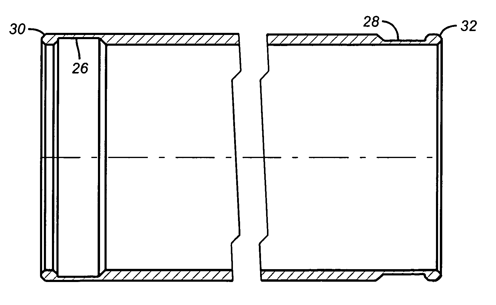
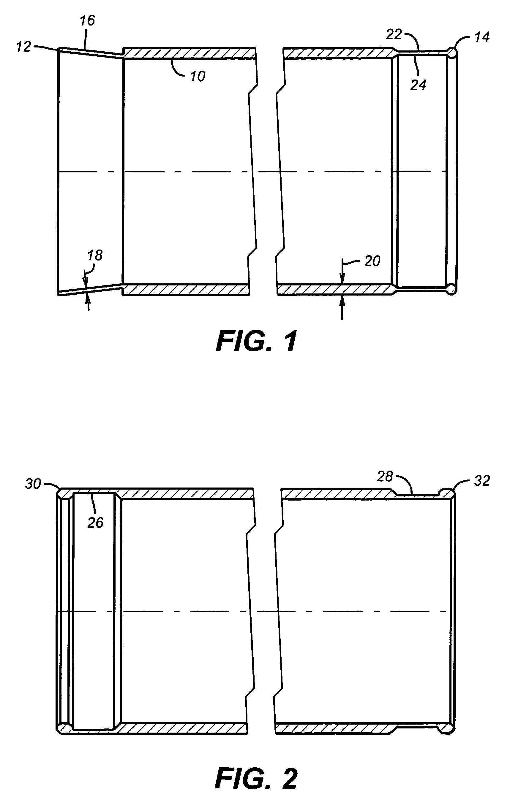
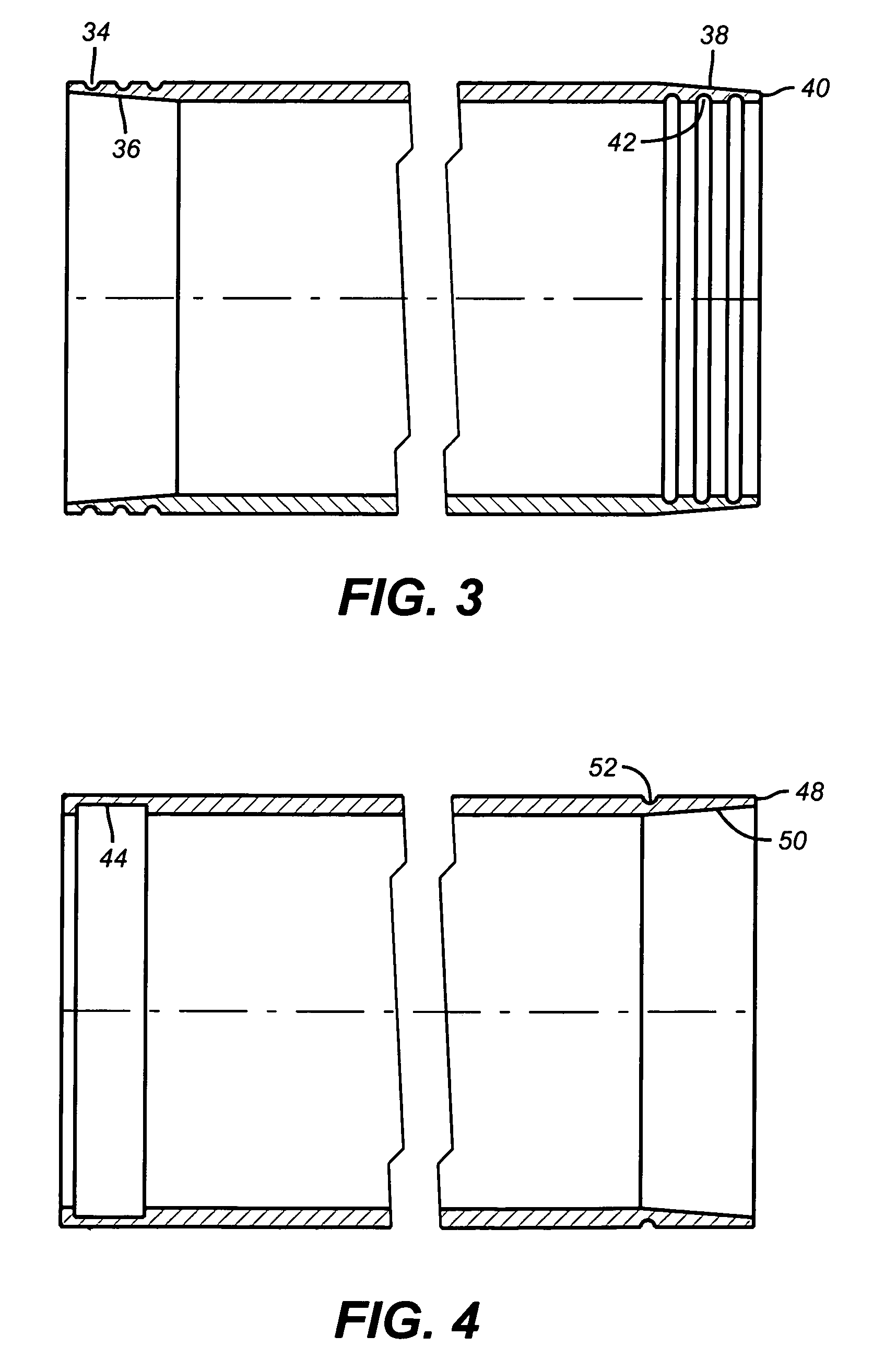
[0018]The present invention seeks to minimize or eliminate end effects resulting from tubing expansion. The end effect is believed to occur is that as a result of high hoop stresses throughout the tubular induced during expansion. For all sections of the tubular not at an end, the section receives support from both sides. Sections at the tubular's ends are supported on only one end. The high hoop stresses are able to overcome this one sided support and deform the tubular inward, reducing the drift diameter.

[0019]The Figures illustrate several approaches to combat this effect. These approaches can be mixed and matched and different approaches can be used at opposed ends. In FIG. 1, the left end is pre-bent outwardly before expansion. After expansion, even if there is an end effect, the pre-bending counteracts it so that the resultant end drift diameter is at least as large as the drift diameter 10 between the ends 12 and 14. The end 12 can be bent outwardly a few degrees or as much a...


PUM


Abstract

A variety of approaches to reducing or eliminating “end effect” or the tendency of tubular ends to reduce in diameter after expansion are disclosed. Some involve pre-bending the ends outwardly while others involve removing material internally or/and externally near the ends. Yet other approaches feature weakening the ends in other ways including penetration of the tubular material using openings of various shapes including slots or/and holes where the openings are between the tube ends or where they can extend on one or both ends all the way to the end of the tubular. Inserts that are softer than the tube material can be placed near the ends. If there is an end effect, then the protruding material can be pushed out of the way or broken off.

Description

FIELD OF THE INVENTION[0001]The field of this invention relates to combating the tendency of expanded tubulars to decrease in drift diameter from the finished expanded diameter at the ends of the tubulars.BACKGROUND OF THE INVENTION[0002]Expanding tubulars has come in vogue in many downhole applications. In a monobore well the finished size of the casing is the same. This is accomplished by inserting casing of a given size and expanding it downhole into a sealing relationship with the previous length of casing already in the bore so that a constant internal clearance diameter, known as drift diameter, is maintained. The drift diameter controls the size of tools that may later be advanced through the expanded tubular string. There are many other applications of expansion technology. Liner strings are hung on casing. Patches for cracked or broken casing or liner are patched with sleeves expanded downhole. Gravel pack screens are expanded to eliminate the annular space previously used ...

Claims


Application Information

Patent Timeline
Patent Type & Authority Patents(United States)
IPC IPC(8): E21B29/00E21B43/10
CPCE21B43/103E21B43/106
Inventor ADAM, MARK K.O'BRIEN, ROBERT S.CARMODY, MICHAEL A.JABS, MATHEW J.GARCIA, DAVID A.
Owner BAKER HUGHES INC
Why Eureka
Try Eureka