Releasable dovetail corner joint

a dovetail and corner joint technology, applied in the field of wooden construction joints, can solve the problems of reducing affecting the structural integrity of the joint, and the components being somewhat loosely fitting, so as to facilitate the adjustment or the assembly of parts, and increase the joint space

Inactive Publication Date: 2007-08-14
DOLAN KEVIN P
View PDF17 Cites 24 Cited by
  • Summary
  • Abstract
  • Description
  • Claims
  • Application Information

AI Technical Summary

Benefits of technology

[0006]Once assembled, the two corner elements form perpendicularly-aligned, vertically-oriented dovetail grooves which can receive corresponding male dovetail members on the side edges of rails or panels to be joined. By turning the fastener(s), the clamp block may be loosened or removed. Loosening the clamp increases the joint space and permits the rail or panel to be repositioned along the length of the dovetail groove. When the fastener(s) are re-tightened, the rail or panel is fixed at the new position. If the fastener(s) are removed completely or grossly loosened, the rail or panel can be assembled or disassembled from the corner leg in the lateral direction. The present assembly therefore provides a corner joint assembly which facilitates the adjustment or the assembly of parts while providing the integrity and strength of dovetail joinery.

Problems solved by technology

The problem with this type of joint is its lack of pull-out resistance which greatly diminishes its structural integrity.
However, while this dovetail configuration provides lateral pull-out resistance, the slidable nature of the joint requires that the components be somewhat loosely fitting.
This has obvious drawbacks to the structural integrity and strength of the joint.
The problem with this system, however, is that the male element is not slidably adjustable and the locking elements are visible on the outside surface of the corner leg which is not aesthetically acceptable for fine furniture or cabinetry.
While these structures have some utility, their use is limited for the following reasons: the tightening wedges can only be applied axially, they cannot be easily removed and reinstalled, and access to the wedges is restricted.

Method used


Image

  • Releasable dovetail corner joint
  • Releasable dovetail corner joint

Examples


Embodiment Construction

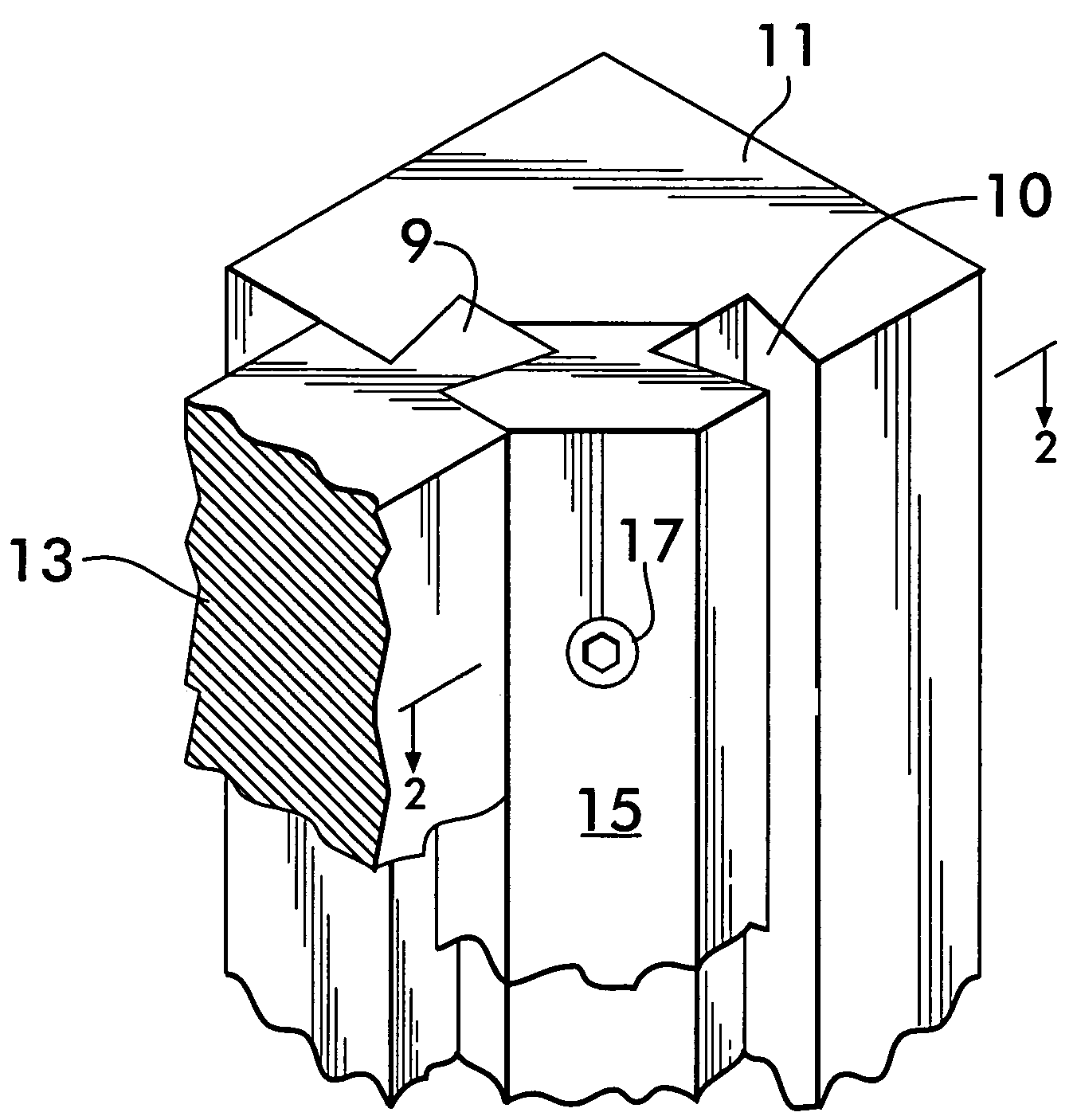
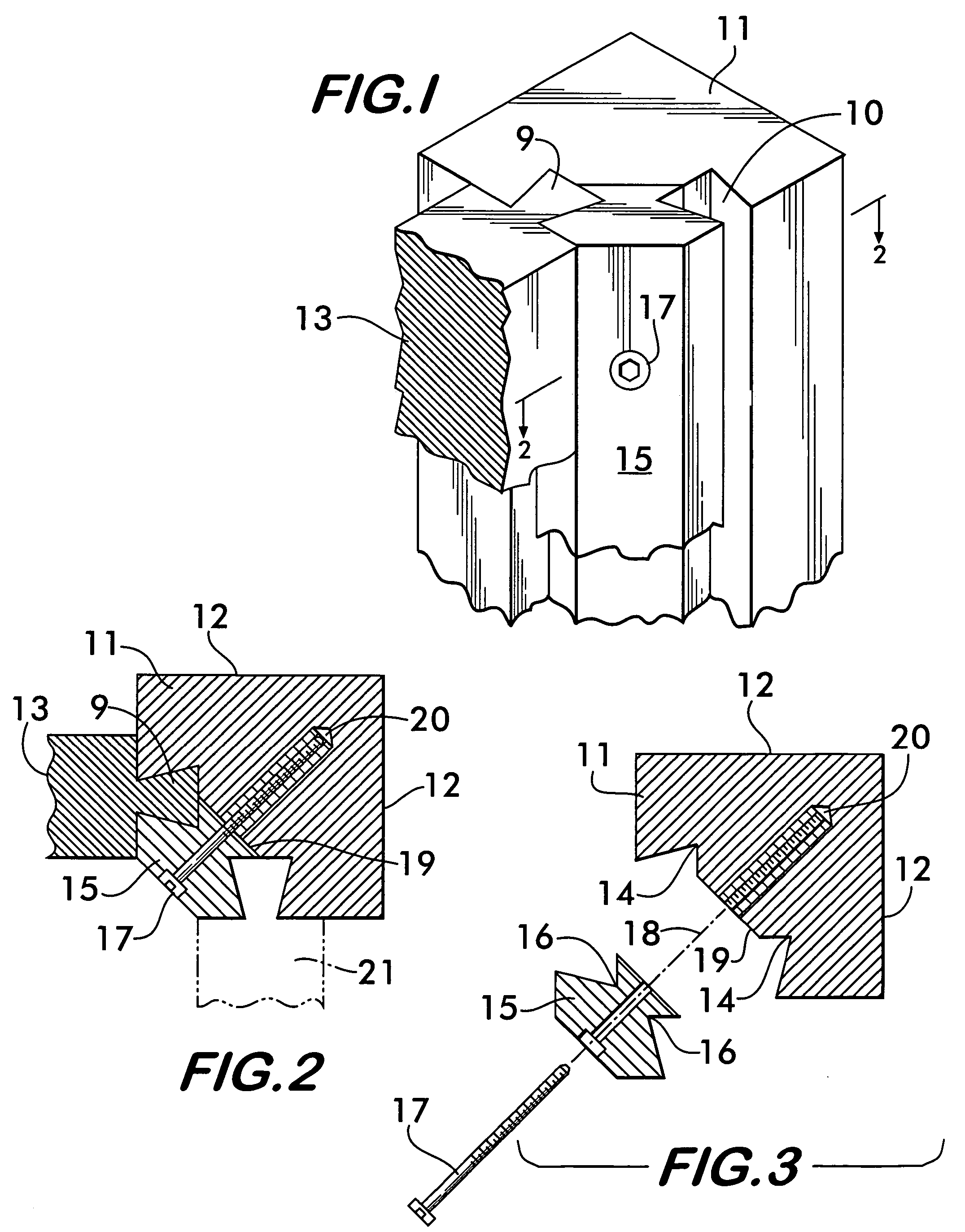
[0012]The invention comprises an assembly of parts for a corner joint for applications including but not limited to furniture and cabinetry. The elements of the assembly may be composed of wood or metal such as extruded aluminum. While the corner joint described in the preferred embodiment includes outside surfaces which are perpendicular, it should be understood that outside angles other than 90 degrees may be employed.

[0013]Referring now to FIG. 1, the invention provides a corner leg 11 with a clamping block 15 which is secured thereto by a fastener 17. As will be described further herein, grooves in the clamping block and in the corner leg are so configured and aligned such that two perpendicularly oriented female dovetail grooves such as groove 10 are formed between them. This enables a structure such as a rail or panel 13 having a male dovetail member 9 to be grasped and securely clamped between the clamping block 15 and the corner leg 11. Greater detail of this assembly of par...


PUM


Abstract

A corner leg assembly comprises two grooved mating elements divided longitudinally which when held together form the female groove portion of two dovetail joints, one on each side facing laterally 90 degrees apart. One of the corner elements is a substantially triangular corner leg having perpendicular outside surfaces and parallel lengthwise L-shaped grooves on a 45 degree inside surface. The second element is a clamp block which includes opposite-facing L-shaped side grooves corresponding (being the mirror image thereof) to the grooves on the corner leg. The clamp block is affixed down the middle of the corner leg along the inside surface by one or more clamping fasteners such as a screw or bolt which passes through the clamp block. By turning the fastener(s), the clamp block may be loosened or removed to vertically adjust a laterally-extending panel or rail member.

Description

FIELD OF THE INVENTION[0001]The invention relates to joinery of wooden construction employed in the field of cabinetry and furniture-making. Specifically, it relates to a dovetail-type corner joint between a corner leg and a rail which includes a releasable clamping element so that the position of the rail along the corner leg may be adjusted or the rail element attached or detached laterally.BACKGROUND OF THE INVENTION AND DESCRIPTION OF PRIOR ART[0002]Various types of joints are well-known in the furniture and cabinet-making arts for connecting elements at right angles which can establish a corner portion of the cabinet or article of furniture. Butt joints, mortise and tenon joints, and dovetail joints are all well-known methods for creating such corner joinery. Typically these are all fixed position joints and when some adjustability of the parts is required, a tongue-and-groove type joint is often used. The problem with this type of joint is its lack of pull-out resistance which...

Claims


Application Information

Patent Timeline
Patent Type & Authority Patents(United States)
IPC IPC(8): A47B13/00
CPCF16B12/125F16B12/46Y10T403/7062Y10T403/42Y10T403/7096Y10T403/7094Y10T403/7067Y10T403/4602Y10T403/73F16B2200/30F16B2200/67
Inventor DOLAN, KEVIN P.
Owner DOLAN KEVIN P
Why Eureka
Try Eureka