Optical scanner

a technology of optical scanners and scanners, applied in the field of optical scanners, can solve problems such as affecting the scanning quality of flatbed image scanners, and achieve the effect of effectively discharging the heat generated by the lamp tub

Inactive Publication Date: 2007-08-14
PRIMAX ELECTRONICS LTD
View PDF5 Cites 4 Cited by
  • Summary
  • Abstract
  • Description
  • Claims
  • Application Information

AI Technical Summary

Benefits of technology

[0009]It is an object of the present invention to provide an optical scanner capable of effectively dissipating the heat generated from the lamp tube therein without considerably increasing the overall volume.

Problems solved by technology

Since the image scanner is developed toward increased resolution and slim volume, the heat generated from the optical scanning module 13 may impair the scanning quality of the flatbed image scanner.

Method used


Image

  • Optical scanner
  • Optical scanner
  • Optical scanner

Examples


Embodiment Construction

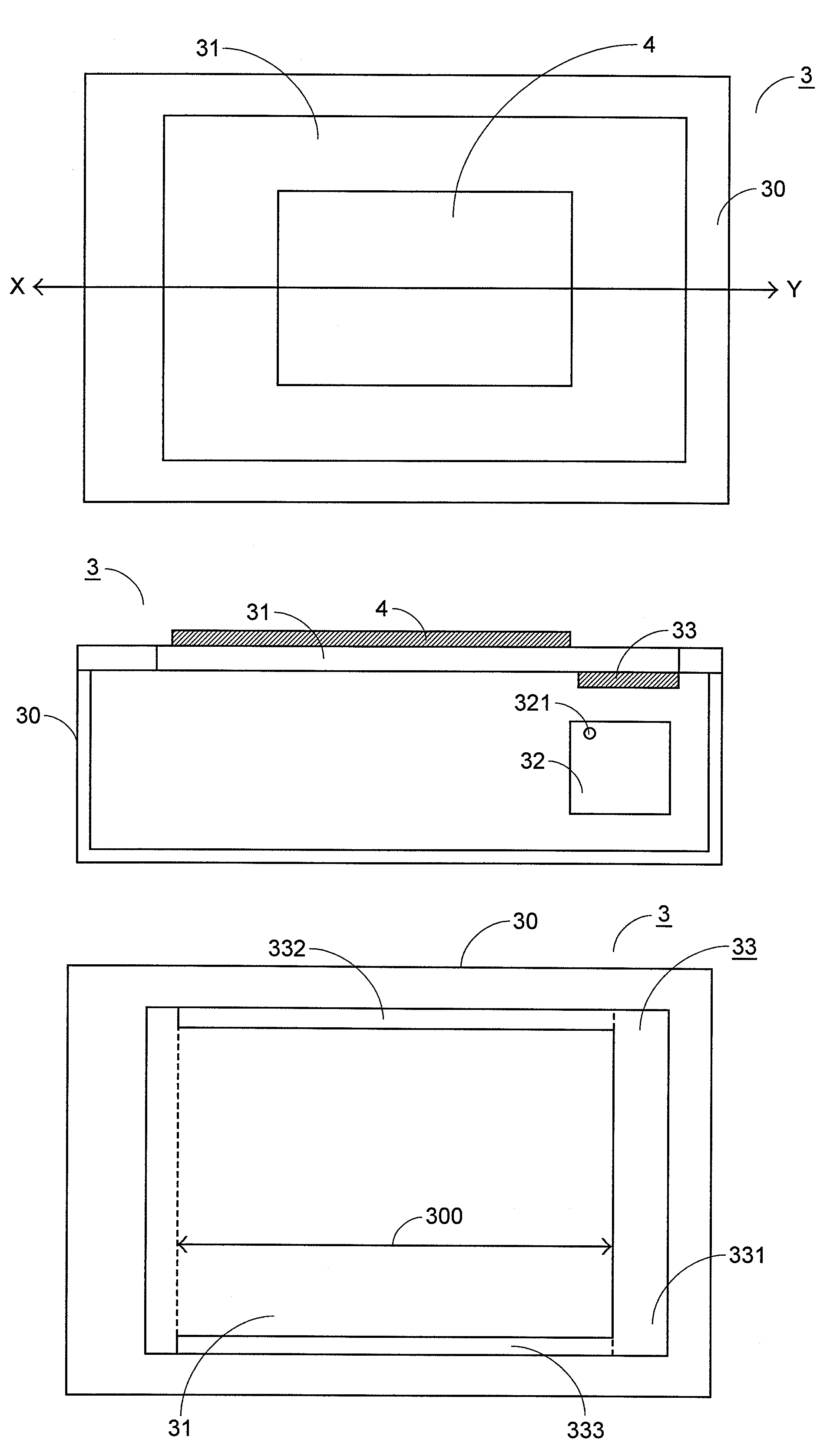
[0024]Please refer to FIGS. 3(a) and 3(b), which are schematic top and cross-sectional views of an optical scanner according to a preferred embodiment of the present invention. An exemplified optical scanner as shown in FIGS. 3(a) and 3(b) is a flatbed image scanner 3 for scanning a document 4. In FIG. 3(a), the flatbed image scanner 3 comprises a housing 30 and a glass platform 31. The glass platform 31 is disposed on the housing 30 and used for placing thereon the document 4 to be scanned. Please refer to FIG. 3(b), which is a cross-sectional view of the flatbed image scanner 3 taken along the line XY. As shown in FIG. 3(b), the flatbed image scanner 3 further comprises an optical scanning module 32 and a heat dissipating member 33, which are disposed inside the housing 30. The optical scanning module 32 has a lamp tube 321 therein for emitting a source light to be projected onto the document 4. Due to the heat generated from the lamp tube 321, the temperature inside the optical s...


PUM


Abstract

An optical scanner for scanning a document includes a housing, a glass platform, an optical scanning module and a heat dissipating member. The glass platform is disposed on the housing for placing thereon the document to be scanned. The optical scanning module is disposed inside the housing for scanning the document. The heat dissipating member is disposed inside the housing and in contact with a first lateral edge of the glass platform for conducting the heat generated from the optical scanning module to the glass platform such that the heat is then radiated from the glass platform to the outside of the housing.

Description

FIELD OF THE INVENTION[0001]The present invention relates to an optical scanner, and more particularly to an optical scanner having a heat dissipating member.BACKGROUND OF THE INVENTION[0002]With increasing development of image processing technologies, flatbed image scanners become essential electronic devices for scanning documents. The images of the scanned documents are converted into image files, which can be stored in a computer or further processed by the computer.[0003]Referring to FIG. 1(a), a schematic view of a flatbed image scanner is illustrated. As shown in FIG. 1(a), the flatbed image scanner 1 comprises a glass platform 11 and an optical scanning module 13. The glass platform 11 is used for placing thereon a document 12 to be scanned. The optical scanning module 13 is the main component of the flatbed image scanner 1. After the document 12 is placed on the glass platform 11, the optical scanning module 13 is moved along the scanning direction so as to scan the documen...

Claims


Application Information

Patent Timeline
Patent Type & Authority Patents(United States)
IPC IPC(8): H04N1/04
CPCH04N1/00989H04N1/1013H04N1/1061
Inventor CHEN, HSI-YUCHEN, KUAN-YANG
Owner PRIMAX ELECTRONICS LTD
Why Eureka
Try Eureka