Base station apparatus and transmission assignment control method

a transmission assignment and base station technology, applied in the field of wireless communication systems, can solve the problems of not always being able to determine the tfrc from the cqi table, the relationship represented in formula (2) may not always be achieved, and the inability to maximize the throughput. achieve the effect of maximizing the throughpu

Inactive Publication Date: 2007-08-14
PANASONIC INTELLECTUAL PROPERTY CORP OF AMERICA
View PDF29 Cites 115 Cited by
  • Summary
  • Abstract
  • Description
  • Claims
  • Application Information

AI Technical Summary

Benefits of technology

[0016]It is therefore an object of the present invention to provide a base station apparatus and a scheduling method that make possible maximization of throughput in consideration of the transmission power of HS-PDSCH.

Problems solved by technology

In the hatched portion of FIG. 2, it may be possible to set a greater TBS than the TBS indicated in the CQI table of FIG. 2, which corresponds to the problem that the throughput is not yet maximized.
When there is a shortage of transmission power resources, the relationship represented in formula (2) may not always be achieved.
Consequently, when formula (2) is not possible, formula (1) is not possible either, and it is not adequate to determine the TFRC from the CQI table based on the CQI's reported from the communication terminal apparatuses without taking into consideration the transmission power of the HS-PDSCH.

Method used


Image

  • Base station apparatus and transmission assignment control method
  • Base station apparatus and transmission assignment control method
  • Base station apparatus and transmission assignment control method

Examples


embodiment 1

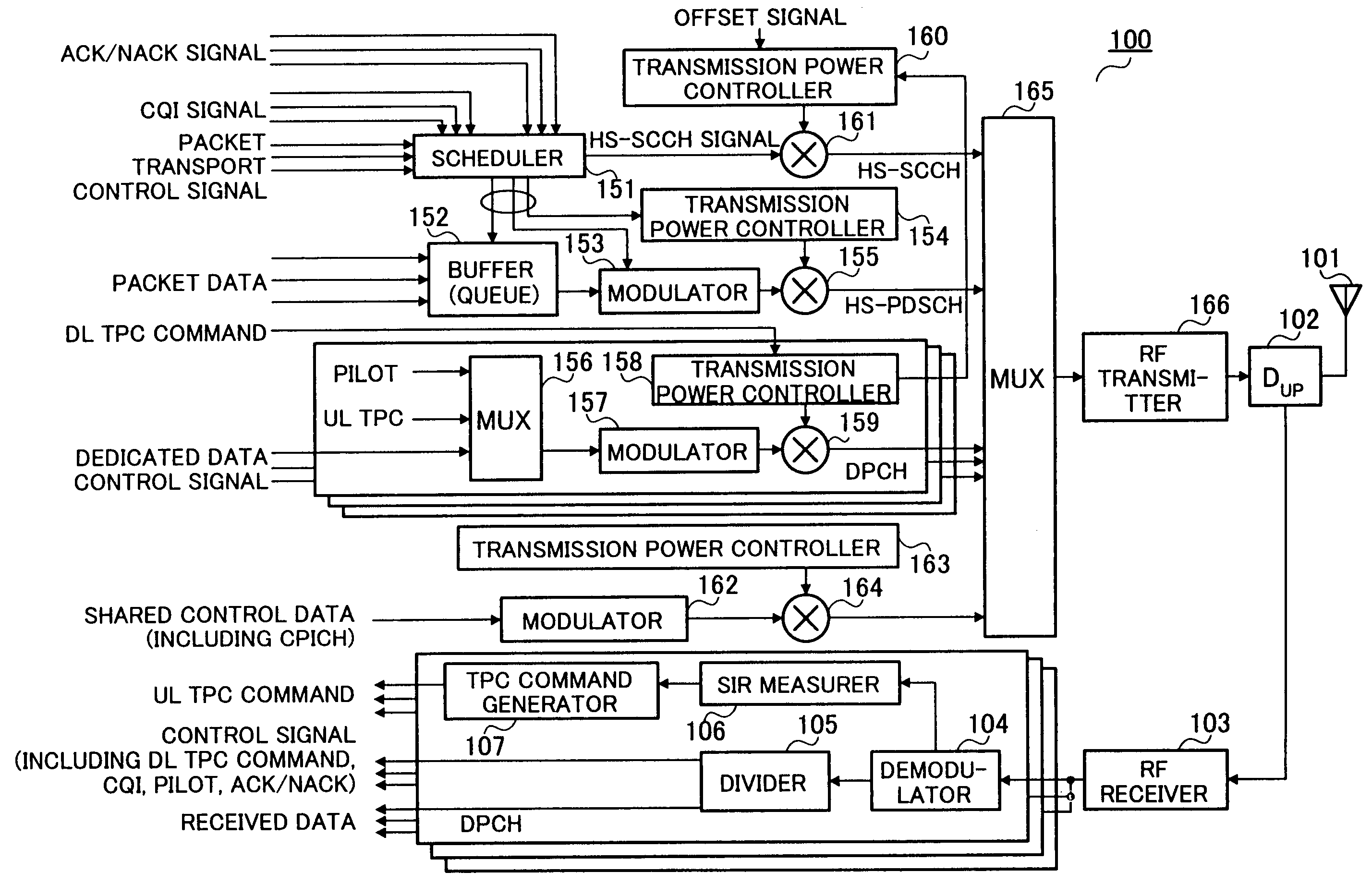
[0042]FIG. 3 is a block diagram showing a configuration of a base station apparatus according to Embodiment 1 of the present invention. The functions of the individual components of base station apparatus 100 shown in FIG. 3 will be described below.

[0043]Duplexer (DUP) 102 outputs a signal received by antenna 101 to RF receiver 103. In addition, duplexer 102 transmits a signal output from RF transmitter 166 by radio from antenna 101.

[0044]RF receiver 103 converts the received signal of radio frequency output from duplexer 102 into a baseband digital signal, and outputs the result to demodulator 104.

[0045]Demodulator 104 performs demodulation processing upon the received baseband signal including despreading, RAKE combining, and error correction decoding, and outputs the result to divider 105. Divider 105 divides the output signal from demodulator 104 into the data and the control signal.

[0046]The control signal separated in divider 105 includes a DL (Down Link)-TPC command, CQI sign...

embodiment 2

[0105]Although the first embodiment has been described using the same TBS table for initial transmission and retransmission without distinguishing between them, the present embodiment will be described with reference to a TBS table that takes retransmission, IR-scheme retransmission in particular, into consideration.

[0106]FIG. 10A is a table with specific TBS values. FIG. 10B shows code rates corresponding to the TBS. For ease of explanation, the number of codes shown is between 1 and 5. In FIG. 10B, most of the code rates are above 0.6 and below 1, and, in comparison to the code rates of FIG. 8, the code rates are limited.

[0107]FIG. 11 shows a comparison of a conventional CQI table and the above-described TBS table. The figure presents a graph in which the vertical axis represents the TBS [bit] and the horizontal axis represents the HS-PDSCH SIR [dB]. The broken line connecting the plots of circles represents the conventional CQI table and the broken line connecting the plots of tr...

embodiment 3

[0118]A case will be described here with this embodiment where the TBS is adjusted in consideration of the amount of data awaiting transmission in a buffer (Queue).

[0119]FIG. 13 is a block diagram showing the internal configuration of the scheduler according to Embodiment 3 of the present invention.

[0120]Parts in FIG. 13 that are identical to the ones in FIG. 5 are assigned the same numerals as in FIG. 5 without further explanations.

[0121]The difference between FIG. 13 and FIG. 5 is that MCS determiner 304 is replaced by MCS determiner 1101.

[0122]Buffer 152 counts the amount of data awaiting transmission (referred to as “the amount of data in queue”) and reports the result to MCS determiner 1101.

[0123]MCS determiner 1101 performs control such that the TBS does not exceed the amount of transmission data by more than a certain range in consideration of the amount of data in queue. For example, when the HS-PDSCH SIR is good and a TBS candidate is determined that exceeds the amount of d...


PUM


Abstract

Transmission destination determiner 301 selects individual communication terminal apparatus as candidates to transmit packets to and determines a transmission destination apparatus based on CQI signals from these communication terminal apparatuses. Transmission power determiner 302 monitors transmission power resources and determines the transmission power of an HS-PDSCH and the transmission power of a pilot channel. HS-PDSCH SIR estimator 303 estimates the SIR of the HS-PDSCH at the transmission destination apparatus based on the CQI signal and the transmission power. MCS determiner 304 determines the maximum TBS based on the HS-PDSCH SIR and indicates an MCS corresponding to the determined TBS to modulator 153. By this means, it is possible to maximize throughput in consideration of the transmission power of the HS-PDSCH.

Description

TECHNICAL FIELD[0001]The present invention relates to a base station apparatus and a transmission assignment control method in a wireless communication system that performs adaptive modulation in high speed downlink packet access, and is suitable to apply to, for instance, a base station apparatus.BACKGROUND ART[0002]In the field of wireless communications, high speed downlink packet transport schemes are being developed, whereby a plurality of communication terminal apparatuses share a high speed and high capacity downlink channel and a base station apparatus transmits packets to the communication terminal apparatuses. High speed downlink packet transport schemes employ scheduling and adaptive modulation techniques for improved transmission rates.[0003]A scheduling technique refers to a technique of having a base station apparatus set the communication terminal apparatus to be the transmission destination (hereinafter referred to as “transmission destination apparatus”) of high spe...

Claims


Application Information

Patent Timeline
Patent Type & Authority Patents(United States)
IPC IPC(8): H04B1/38H04M1/00H04B7/005H04L27/00H04B7/26H04J13/00H04L1/18H04W28/18H04W52/04H04W72/04H04W72/12
CPCH04L1/0026H04W52/16H04L1/0003H04L1/0009H04L1/1812
Inventor IOCHI, HITOSHI
Owner PANASONIC INTELLECTUAL PROPERTY CORP OF AMERICA
Why Eureka
Try Eureka