Modular surface mount fluid system

Active Publication Date: 2007-08-21
SWAGELOK CO
View PDF34 Cites 16 Cited by
  • Summary
  • Abstract
  • Description
  • Claims
  • Application Information

AI Technical Summary

Benefits of technology

[0010]The invention also provides an air actuated surface mount flow control valve comprising a valve body having a mounting flange connected thereto and the flange being substantially planar and having an inlet passage located about the center of the flange and an outlet passage located adjacent the inlet passage, the body further comprising a cavity in fluid communication with the inlet pas

Problems solved by technology

These type of connections may be undesirable in some applications because they add additional time and cost for welding operations, unnecessary space between components and make it difficult to replace a component located between other components.
Further, these systems are typically custom designed and manufactured which make the manufacturing costs and procurement of replacement parts quite expensive.
However, these fluid systems have the di

Method used


Image

  • Modular surface mount fluid system
  • Modular surface mount fluid system
  • Modular surface mount fluid system

Examples


Embodiment Construction

[0030]The present invention is directed to a modular surface mount fluid system and surface mount modular flow valves for use therewith. The modular surface mount fluid system is described in detail in Section I, while the surface mount modular flow valves are described in more detail in sections II and III.

MODULAR SURFACE MOUNT FLUID SYSTEM

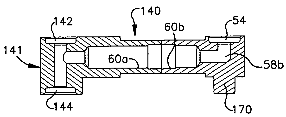
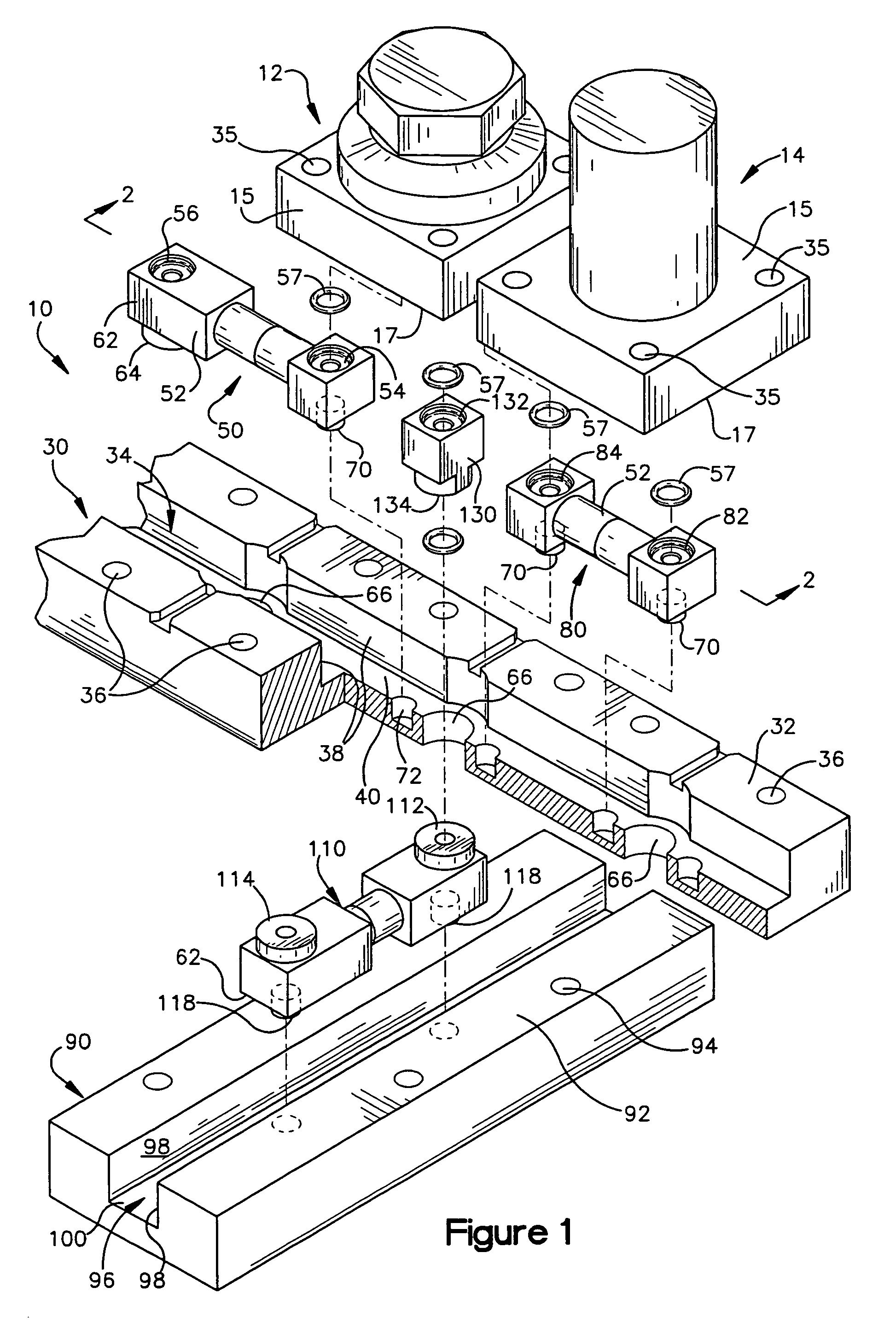
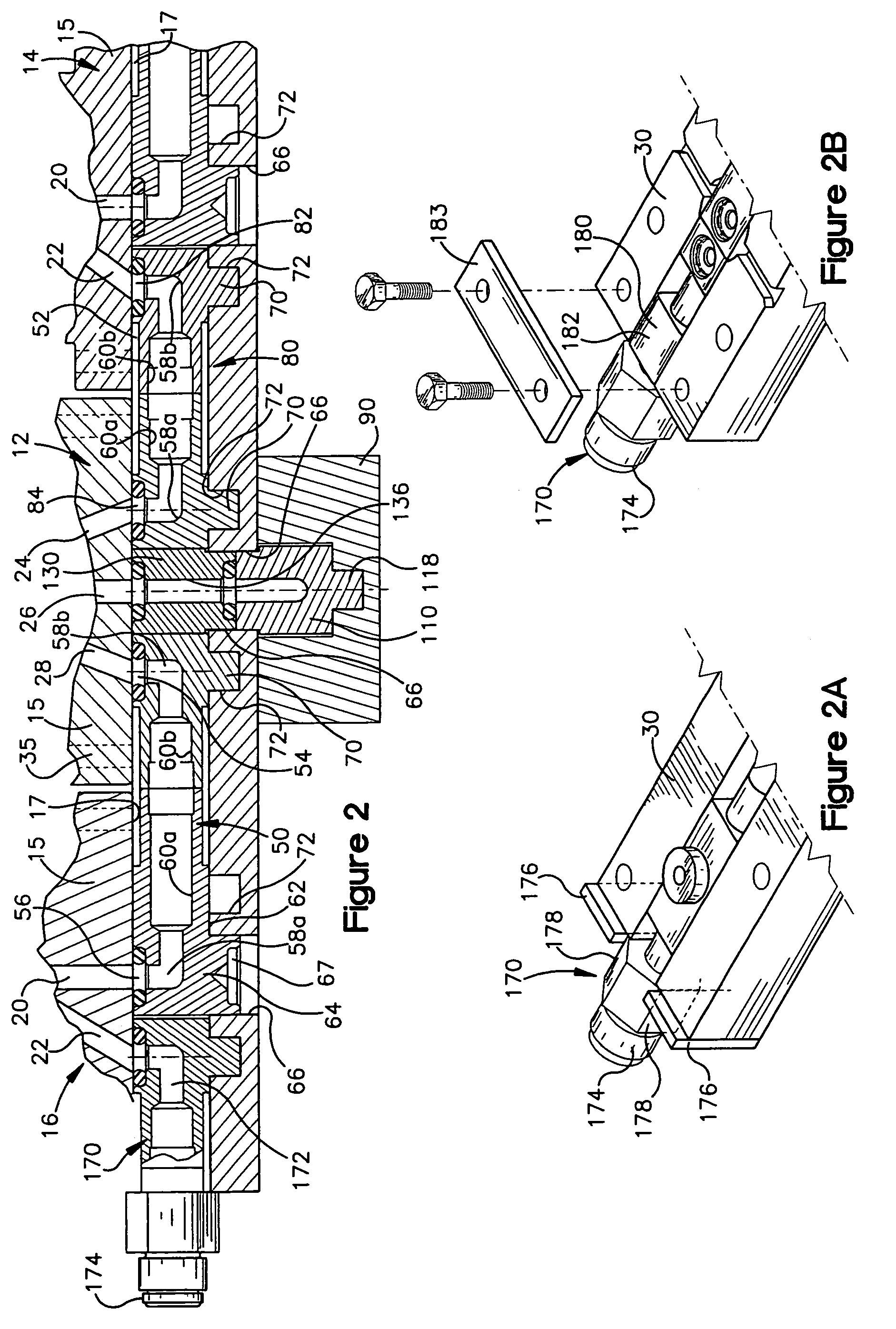
[0031]Referring now to FIG. 1, an exploded view of an exemplary modular fluid system 10 is shown for use with surface mount fluid components such as valve 12 and filter 14. Other fluid components such as pressure transducers (not shown), mass flow controllers (not shown) and the like may also be utilized in conjunction with the modular manifold system of the invention. As shown in FIGS. 1 and 2, the surface mount components 12,14,16 each have a square mounting flange 15 of a standard size with at least one inlet port and at least one outlet port located adjacent the inlet port. The inlet / outlet ports are located on the bottom planar mounting surf...


PUM


Abstract

The present invention provides for a bridge fitting for use in a fluid manifold system for being in fluid communication with two or more surface mounted fluid components having an inlet port and an adjacent outlet port. The invention also provides for a housing with a first port connected to a second port, with an internal fluid passageway joining the first and second ports and at least one projection extending from the housing. The bridge fittings may be mounted in a channel block having a groove and an aligned hole for receiving the projection. Another embodiment of the invention provides for a modular surface mount check valve with a valve body having a mounting flange connected thereto, the flange being substantially planar and having an inlet passage located about the center of the flange and an outlet passage located adjacent the inlet passage. The body further comprises a valve chamber in fluid communication with the inlet passage and the outlet passage, the chamber further comprising a valve seat formed at the juncture of the inlet passage and the chamber, and a poppet positioned in the chamber, and a spring mounted in the valve chamber for biasing the poppet towards the valve seat. The invention also provides an air actuated surface mount flow control valve comprising a valve body having a mounting flange connected thereto and the flange being substantially planar and having an inlet passage located about the center of the flange and an outlet passage located adjacent the inlet passage, the body further comprising a cavity in fluid communication with the inlet passage and the outlet passage, a stem positioned in the cavity, and a spring mounted in the cavity for biasing a first end of the stem in sealing engagement with the inlet passage and the outlet passage, the stem further comprising an internal fluid passageway in fluid communication with an actuator fluid compartment located under a lower surface of the stem, and the external source of pressure.

Description

PRIORITY CLAIM[0001]This application claims the benefit of U.S. provisional (60 / 429,088) filed on Nov. 26, 2002, Express Label No. EL084747996US, and entitled Modular Surface Mount Manifold System, and U.S. provisional (60 / 433,371) filed on Dec. 13, 2002, Express Label No. EL084748033US, and entitled Modular Surface Mount Fluid System which is hereby incorporated by reference in its entirety.FIELD OF THE INVENTION[0002]The inventions disclosed herein relates in general to manifolds and valves for fluid systems.BACKGROUND OF THE INVENTION[0003]Various industrial manufacturing processes often require the use of gasses and fluids which are controlled by systems made up of valves, regulators, pressure transducers, mass flow controllers and the like. These components are typically connected together by the use of welded tubing and compression fittings and mounted on a vertical panel. These type of connections may be undesirable in some applications because they add additional time and co...

Claims


Application Information

Patent Timeline
IPC IPC(8): F16K11/00F15B13/00F15B13/08F16K27/00F16L39/00
CPCF15B13/0814F15B13/0817F15B13/0825F16L39/00F15B13/0892F16K27/003F15B13/086F16K11/22Y10T137/87885F16J15/021F16J15/062
Inventor PERUSEK, ROBERT V.HASAK, DAVID J.KALATA, GREGORY S.NORDSTROM, DOUGLAS A.MARUNA, TIMOTHY
Owner SWAGELOK CO
Why Eureka
Try Eureka