Liner hanger with slip joint sealing members and method of use

a technology of sealing member and liner, which is applied in the direction of sealing/packing, drilling pipes, and wellbore/well accessories, etc., can solve the problems of not being able to adapt to variable loading conditions, and conventional tubular liners used for repairing damaged sections of wellbore casings suffer from a number of serious drawbacks

Inactive Publication Date: 2007-08-21
ENVENTURE GLOBAL TECH LLC
View PDF1203 Cites 19 Cited by
  • Summary
  • Abstract
  • Description
  • Claims
  • Application Information

AI Technical Summary

Benefits of technology

[0007]According to another aspect of the present invention, an apparatus for repairing an opening in a wellbore casing is provided that includes a tubular support member including a first passage, an expansion cone coupled to the tubular support member including a second pas

Problems solved by technology

However, conventional tubular liners used for repairing damaged sections of wellbore casings suffer from a number of serious drawback.
For example

Method used


Image

  • Liner hanger with slip joint sealing members and method of use
  • Liner hanger with slip joint sealing members and method of use
  • Liner hanger with slip joint sealing members and method of use

Examples


Embodiment Construction

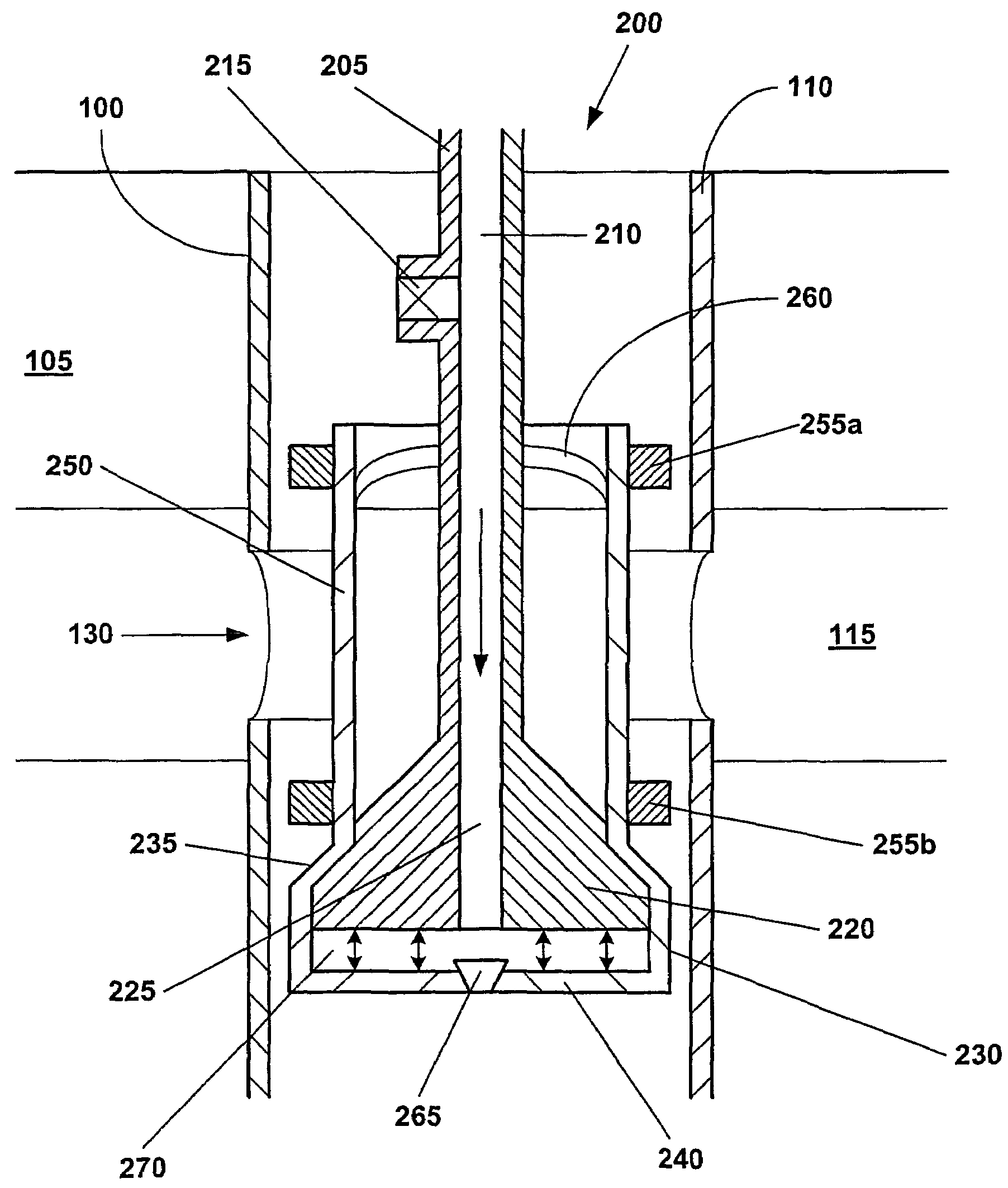
[0021]An apparatus and method for repairing an opening in a damaged section of a wellbore casing within a subterranean formation is provided. The apparatus and method provides a system for repairing an opening in a damaged section of a wellbore casing within a subterranean formation in which a tubular member is radially expanded into contact with the wellbore casing. The physical connection between the radially expanded tubular member and the wellbore casing is preferably compliant and permits movement of the radially expanded tubular member relative to the wellbore casing in at least the longitudinal direction. In this manner, the radially expanded tubular member is capable of absorbing a wide range of loading conditions.

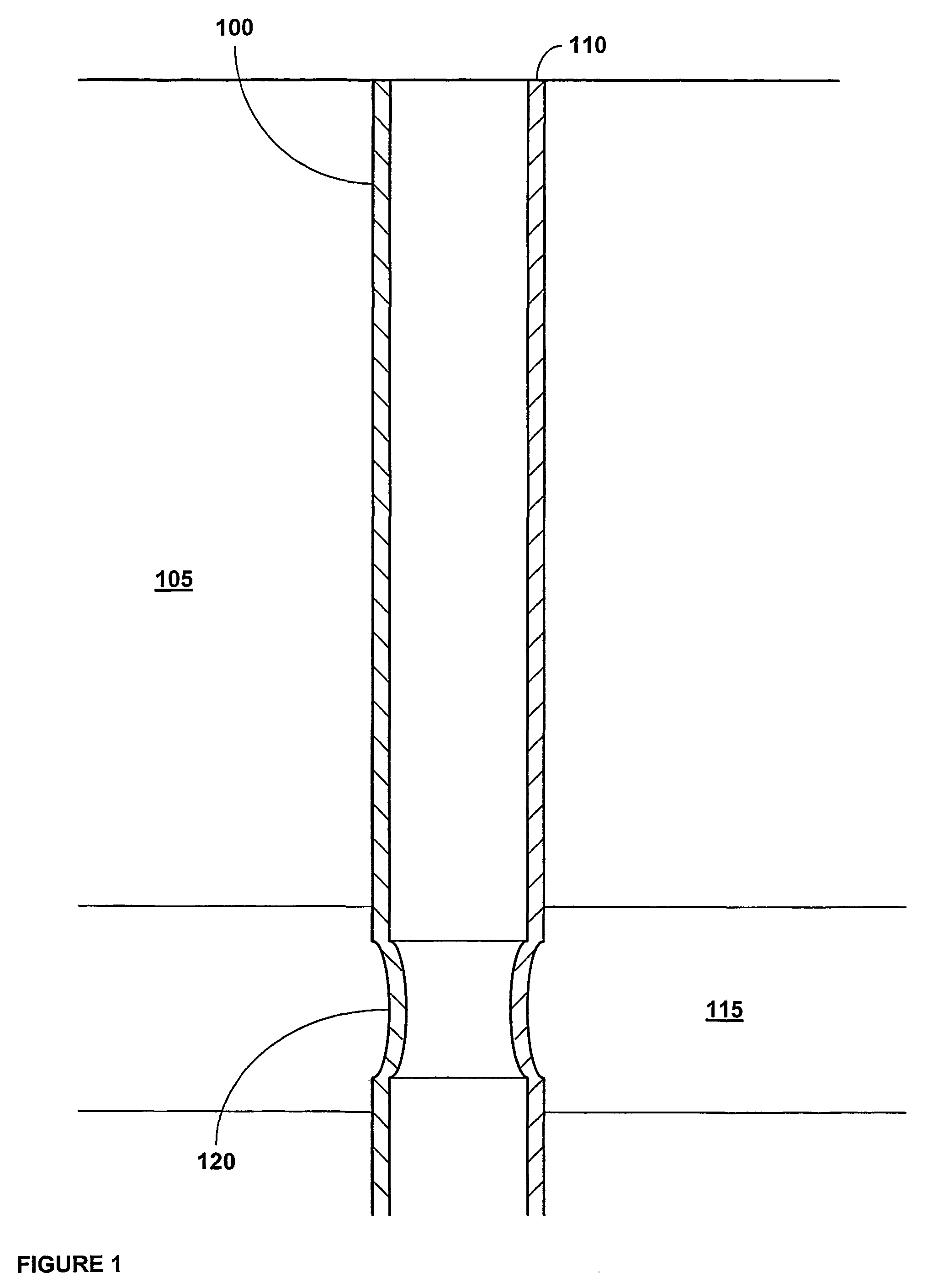
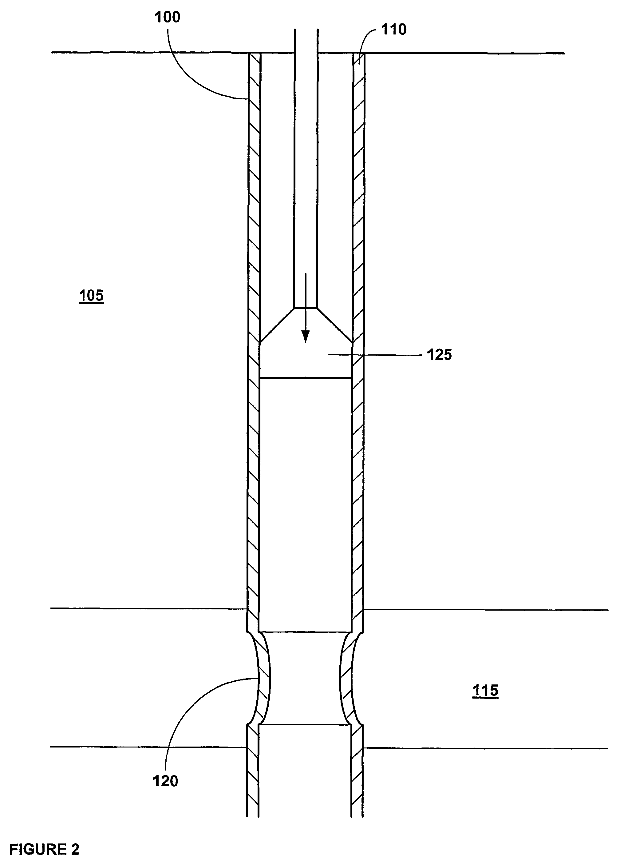
[0022]Referring initially to FIG. 1, a wellbore 100 positioned within a subterranean formation 105 includes a preexisting casing 110 that traverses a producing formation 115. The portion of the casing 110 that traverses the producing formation 115 includes a damage...


PUM


Abstract

An apparatus (200) and method for repairing an opening (130) in a wellbore casing (110). The apparatus (200) and method couple a floating tubular (250) member in opposing relation to the opening (130) in the wellbore casing (110).

Description

CROSS REFERENCE TO RELATED APPLICATIONS[0001]This application is related to the following applications: (1) U.S. Pat. No. 6,497,289, which was filed as U.S. patent application Ser. No. 09 / 454,139, filed on Dec. 3, 1999, which claims priority from provisional application No. 60 / 111,293, filed on Dec. 7, 1998, (2) U.S. patent application Ser. No. 09 / 510,913, filed on Feb. 23, 2000, which claims priority from provisional application No. 60 / 121,702, filed on Feb. 25, 1999, (3) U.S. Pat. No. 6,823,937, which was filed as U.S. patent application Ser. No. 09 / 502,350, filed on Feb. 10, 2000, which claims priority from provisional application No. 60 / 119,611, filed on Feb. 11, 1999, (4) U.S. Pat. No. 6,328,113, which was filed as U.S. patent application Ser. No. 09 / 440,338, filed on Nov. 15, 1999, which claims priority from provisional application No. 60 / 108,558, filed on Nov. 16, 1998, (5) U.S. patent application Ser. No. 10 / 169,434, filed on Jul. 1, 2002, which claims priority from provisio...

Claims


Application Information

Patent Timeline
IPC IPC(8): E21B43/10E21B29/10E21B33/124
CPCE21B29/10E21B33/124E21B43/103
Inventor COOK, ROBERT LANCERING, LEV
Owner ENVENTURE GLOBAL TECH LLC
Why Eureka
Try Eureka