Slip joint of steering apparatus for vehicle

a technology for steering apparatus and slip joint, which is applied in mechanical apparatus, couplings, transportation and packaging, etc., can solve the problems of rattling noise and the inability of the ball to smoothly transfer the rotational force of the input shaft, and achieve the effect of improving the stability and durability of the slip joint and increasing the torsional rigidity of the slip bush

Active Publication Date: 2009-06-04
HL MANDO CORP
View PDF10 Cites 18 Cited by
  • Summary
  • Abstract
  • Description
  • Claims
  • Application Information

AI Technical Summary

Benefits of technology

[0020]Accordingly, the present disclosure provides a slip joint of a steering apparatus for a vehicle, in which an elastic part transfers power while compensating for clearance even when a ball disposed between an inner member and an outer member of a slip joint is worn away or damaged due to abrasion, so that a rattling noise generated due to clearance is removed, and steering stability and durability of the slip joint can be improved by increasing torsional rigidity of a slip bush.

Problems solved by technology

This is because a typical type shaft assembling structure can not transfer power.
However, the conventional universal joint 100 of a steering apparatus for a vehicle has a problem in that when bending force or torsion force generated due to large load exerted from the outside is applied to the universal joint 100, the ball 150 disposed between the outer member 122 and the inner member 124 rotates while receiving the load.
As a result, a deformation phenomenon where the ball 150 is damaged or deteriorated occurs so that the ball can not smoothly transfer rotational force of the input shaft.
Also, because the ball disposed between the guide recess 160 and the guide recess 170 is worn away due to frequent friction, etc., clearance is generated so that a rattling noise is generated.

Method used


Image

  • Slip joint of steering apparatus for vehicle
  • Slip joint of steering apparatus for vehicle
  • Slip joint of steering apparatus for vehicle

Examples


first embodiment

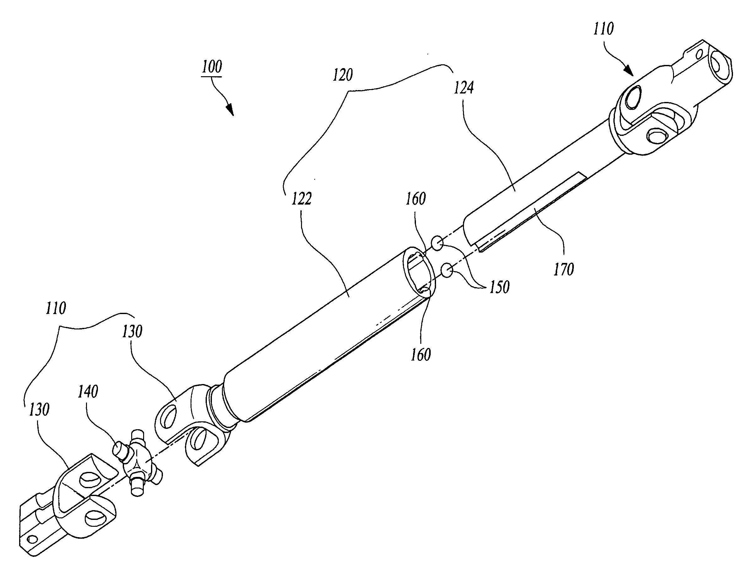
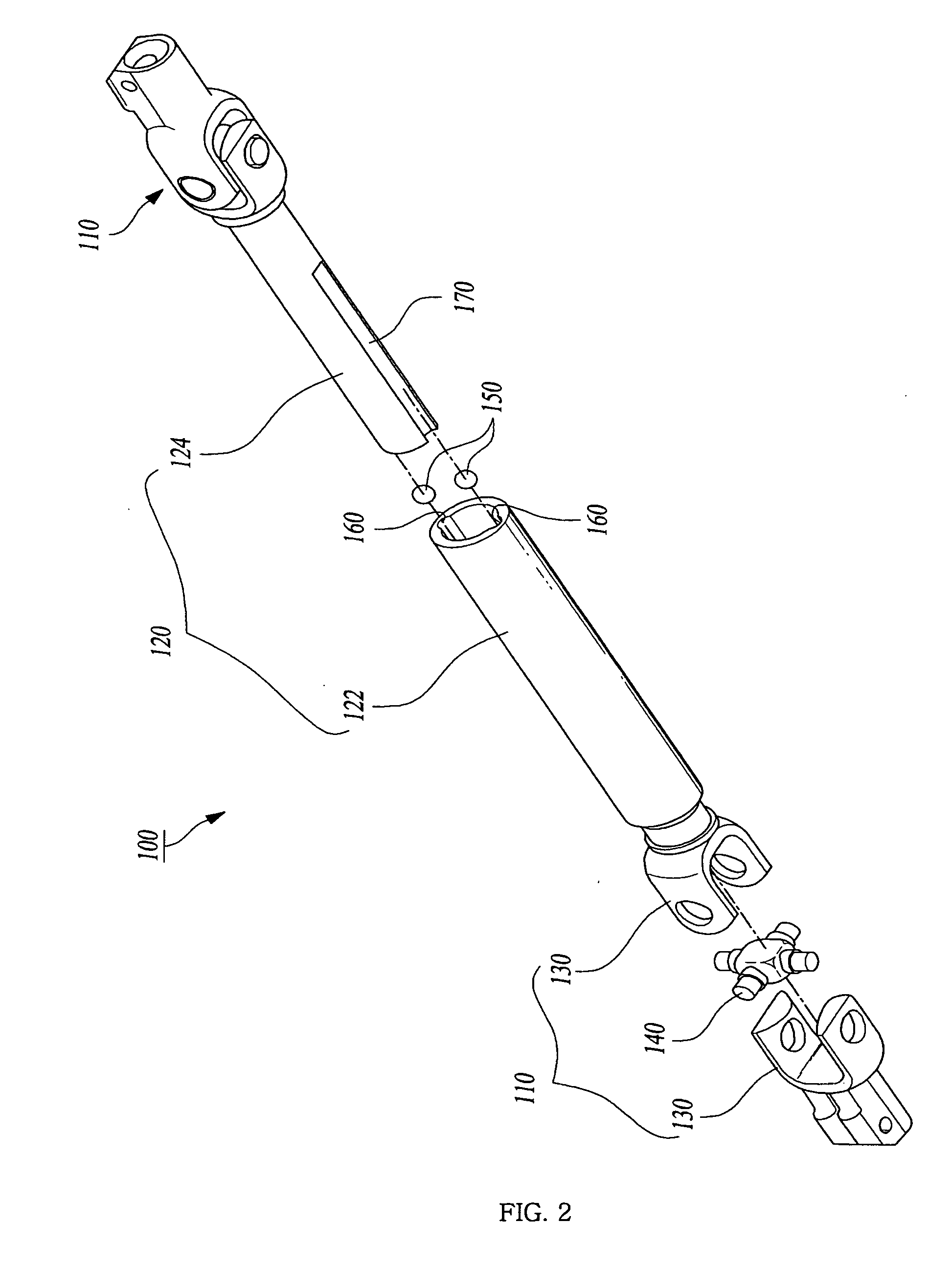
[0041]As shown in FIGS. 4a to 5, a slip joint 120 of a steering apparatus for a vehicle according to the present invention includes an outer member 122, an inner member 124 and a slip bush 300.

[0042]The outer member 122 has a hollow interior and has one side connected to the yoke joint 110. A plurality of first assembling recesses 360 are formed on the inner circumferential surface of the outer member in an axial direction.

[0043]The inner member 124 has one side connected with the yoke joint 110 and the other side inserted within the outer member 122. A plurality of second assembling recesses 370 are formed on an outer circumferential surface of the inner member 124 in an axial direction.

[0044]The slip bush 300 has a hollow cylindrical shape, and a plurality of mounting parts 310 and a plurality of elastic parts 320 are formed on the slip bush by turns in such a manner that they are spaced a predetermined distance from each other. The slip bush 300 is inserted between the outer memb...

second embodiment

[0069]As shown in FIGS. 7 and 8, the slip joint of the steering apparatus for a vehicle according to the present invention includes an inner member 124 having a plurality of second assembling recesses 370 formed on an outer circumferential surface thereof while having a long shape formed in an axial direction; an outer member 122 having a plurality of first assembling recesses 360, which are formed on an inner circumferential surface thereof while corresponding to the second assembling recesses 370 and have a long shape formed in an axial direction, the inner member 124 being inserted into the outer member 122; and a slip bush 300, which has a cylindrical shape having a hollow interior and is inserted between the outer member 122 and the inner member 124, the slip bush 300 having elastic parts 320 and mounting parts 310 formed on a circumferential surface of the slip bush along an axial direction in such a manner that they are spaced from each other, the elastic parts 320 and the mo...

third embodiment

[0083]As shown in FIGS. 9 and 10, the slip joint of the steering apparatus for a vehicle according to the present invention includes an inner member 124 having a plurality of second assembling recesses 370 formed on an outer circumferential surface thereof while having a long shape formed in an axial direction; an outer member 122 allowing the inner member 124 to be inserted thereinto, the outer member having a plurality of first assembling recesses 360, which are formed on an inner circumferential surface thereof while corresponding to the second assembling recesses 370 and have a long shape formed in an axial direction, and protrusions 315, which protrude from the inner circumferential surfaces of the first assembling recesses 360 while having a long shape formed in an axial direction; and a slip bush 300, which has a cylindrical shape having a hollow interior and is inserted between the outer member 122 and the inner member 124, including elastic parts 320 of a cylindrical shape ...


PUM


Abstract

Disclosed is a slip joint of a steering apparatus for a vehicle, the slip joint including: an outer member having a plurality of first assembling recesses; an inner member being inserted within the outer member and having a plurality of second assembling recesses; and a slip bush, which is inserted between the outer member and the inner member and has mounting parts, into which balls and rollers inserted, and elastic parts having one side cut out in an axial direction, each mounting part having a plurality of first mounting holes and a plurality of second mounting holes. Each elastic part transfers power while compensating for clearance even when the balls disposed between the inner member and the outer member of the slip joint are worn away so that a rattling noise generated due to clearance is removed, and steering stability and durability of the slip joint can be improved.

Description

TECHNICAL FIELD [0001]The present disclosure relates to a slip joint of a steering apparatus for a vehicle.[0002]More particularly, the embodiments of the invention relates to a slip joint of a steering apparatus for a vehicle, in which an elastic part transfers power while compensating for clearance even when a ball disposed between an inner member and an outer member of a slip joint is worn away or damaged due to abrasion, so that a rattling noise generating due to clearance is removed, and steering stability and durability of the slip joint can be improved by increasing torsional rigidity of a slip bush.[0003]Also, the ball makes contact with four points within the slip bush so as to decrease frictional force, and the slip bush can smoothly slide even if the ball is deformed.BACKGROUND ART[0004]In a steering apparatus for a vehicle, if a driver rotates a steering wheel in a desired direction, a steering shaft connected to the steering wheel rotates. Accordingly, the steering shaf...

Claims


Application Information

Patent Timeline
Patent Type & Authority Applications(United States)
IPC IPC(8): F16D3/224B62D1/20F16D3/06
CPCF16D3/065F16C3/035F16C2326/24F16C29/007
Inventor JUNG, YOUNG-SOCKPARK, JUNG-SIKPARK, YOUNG-MOON
Owner HL MANDO CORP
Why Eureka
Try Eureka