Method of forming a slip joint

a technology of slip joint and axial movement, which is applied in the direction of couplings, manufacturing tools, mechanical equipment, etc., can solve the problems of affecting the operation of the slip joint assembly, and unable to meet the needs of relative axial movemen

Inactive Publication Date: 2006-03-07
DANA AUTOMOTIVE SYST GRP LLC
View PDF11 Cites 17 Cited by
  • Summary
  • Abstract
  • Description
  • Claims
  • Application Information

AI Technical Summary

Benefits of technology

[0006]This invention relates to an improved method for forming tubing around a tube seal during the manufacture of a splined connection between first and second members of a driveshaft assembly. According to this invention there is provided method of forming a slip joint, the method including providing an inner tube having a plurality of axially extending external splines. A circumferential seal is applied around the inner tube, and an outer tube is placed around the inner tube and the seal. Radially inward pressure is applied on the outer tube to deform the outer tube and cause it to conform to the shape of the inner tube, and thereby forming splines on the inner surface of the outer tube. The splines on the outer surface of the inner tube and the splines on the inner surface of the outer tube are configured to cooperate together to form a slip joint. According to this invention there is also provided method of forming a slip joint, the method including providing a forming mandrel having a plurality of axially extending external splines, placing an inner tube circumferentially about the mandrel, and applying radially inward pressure on the inner tube to deform the inner tube and cause it to conform to the shape of the mandrel. The deformation step forms splines on the outer surface of the inner tube. A circumferential seal is applied around the inner tube, and an outer tube is placed around the inner tube and the seal. Radially inward pressure is applied on the outer tube to deform the outer tube and cause it to conform to the shape of the inner tube, and thereby forming splines on the inner surface of the outer tube. The splines on the outer surface of the inner tube and the splines on the inner surface of the outer tube are configured to cooperate together to form a slip joint.

Problems solved by technology

Not only must a typical drive train system accommodate a limited amount of angular misalignment between the source of rotational power and the rotatably driven device, but it must also typically accommodate a limited amount of relative axial movement therebetween.
However, the outwardly extending splines of the male member can slide relative to the inwardly extending splines of the female member to allow a limited amount of relative axial movement to occur between the engine / transmission assembly and the axle assembly of the drive train system.
Such contaminants can adversely affect the operation of the slip joint assembly and cause premature failure thereof.
Consequently, the additional machining makes the driveshaft assembly expensive to manufacture.
Additionally, the boot is susceptible to failure because of its external positioning.

Method used


Image

  • Method of forming a slip joint
  • Method of forming a slip joint
  • Method of forming a slip joint

Examples


Embodiment Construction

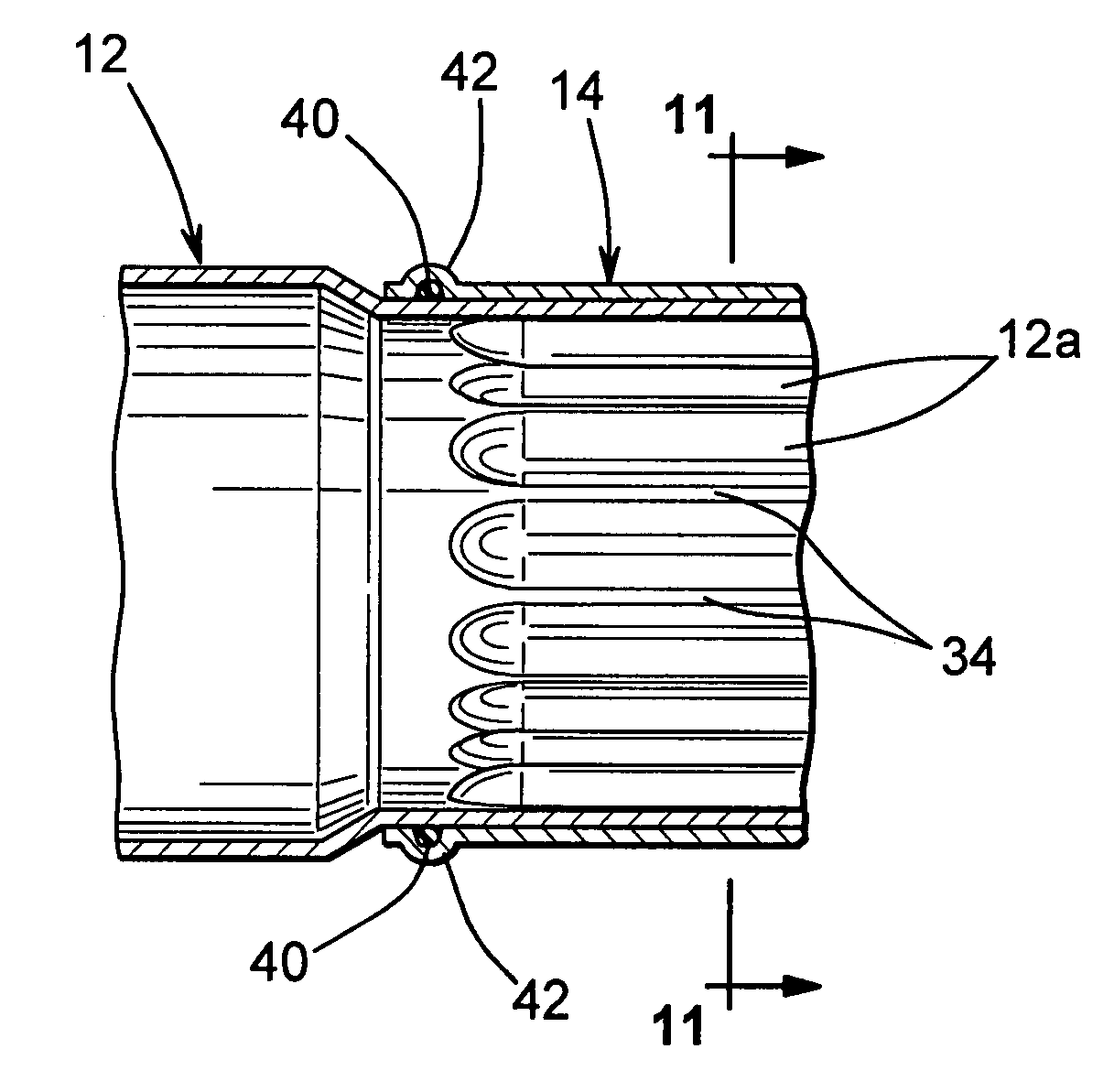
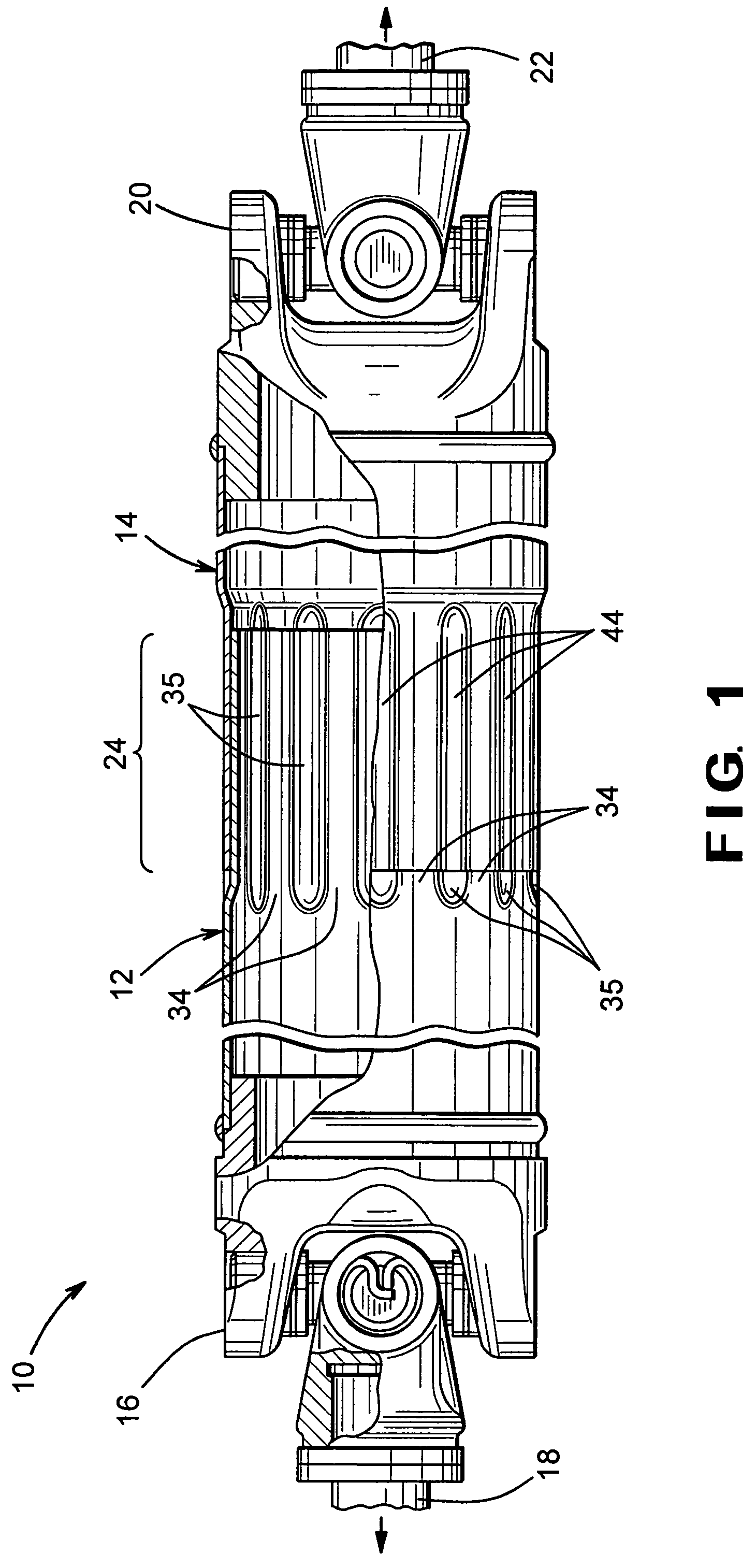
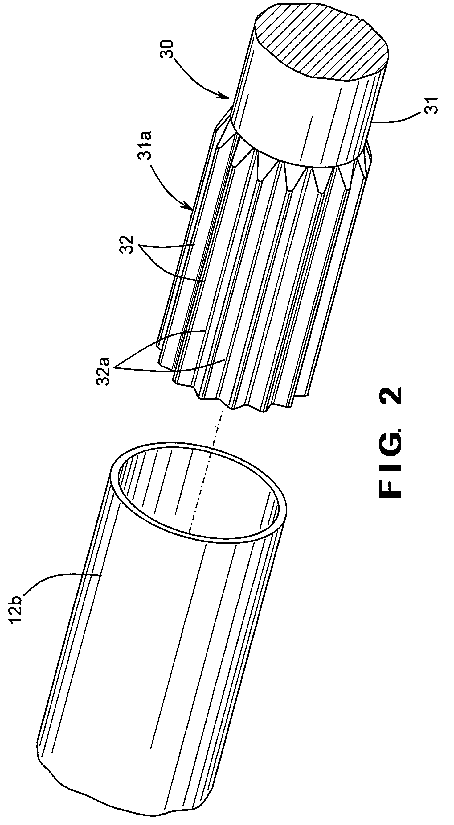
[0018]Referring now to the drawings, there is illustrated apparatus for carrying out the method for forming a slip joint in accordance with this invention. As shown in FIG. 1, a driveshaft assembly, indicated generally at 10, is composed of an inner tube 12, which is a yoke shaft, received in an axially overlapping or telescoping manner within an outer tube 14, which is a slip yoke. In the illustrated embodiment, the inner tube 12 is connected to the front universal joint 16, with the universal joint 16 being connected to the output shaft 18 of a transmission, not shown. The outer tube 14 is connected to the rear universal joint 20, which is connected to the input shaft 22 of an axle assembly, also not shown. If desired, however, the inner tube 12 may be connected to the rear universal joint 20, while the outer tube 14 is connected to the front universal joint 16.

[0019]The driveshaft 10 is generally hollow and cylindrical in shape, having an axial length which varies in accordance w...


PUM

PropertyMeasurementUnit
pressureaaaaaaaaaa
flexibleaaaaaaaaaa
poweraaaaaaaaaa

Abstract

A method of forming a slip joint includes providing a forming mandrel having a plurality of axially extending external splines, placing an inner tube circumferentially about the mandrel, and applying radially inward pressure on the inner tube to deform the inner tube and cause it to conform to the shape of the mandrel. The deformation step forms splines on the outer surface of the inner tube. A circumferential seal is then applied around the inner tube, and an outer tube is placed around the inner tube and the seal. Radially inward pressure is applied on the outer tube to deform the outer tube and cause it to conform to the shape of the inner tube, and thereby forming splines on the inner surface of the outer tube. The splines on the outer surface of the inner tube and the splines on the inner surface of the outer tube are configured to cooperate together to form a slip joint.

Description

BACKGROUND OF THE INVENTION[0001]This invention relates in general to vehicular driveshaft assemblies and in particular to a method of forming tubing around a tube seal during the manufacture of a splined connection between first and second members of a driveshaft assembly.[0002]Drive train systems are widely used for generating power from a source and for transferring such power from the source to a driven mechanism. Frequently, the source generates rotational power, and such rotational power is transferred from the source to a rotatably driven mechanism. For example, in most land vehicles in use today, an engine / transmission assembly generates rotational power, and such rotational power is transferred from an output shaft of the engine / transmission assembly through a driveshaft assembly to an input shaft of an axle assembly so as to rotatably drive the wheels of the vehicle. To accomplish this, a typical driveshaft assembly includes a hollow cylindrical driveshaft tube having a pa...

Claims


Application Information

Patent Timeline
Patent Type & Authority Patents(United States)
IPC IPC(8): B23P17/00F16C3/03F16D3/06F16D3/84
CPCF16C3/03F16D3/06F16D3/84Y10T29/49927Y10T29/49805Y10T29/49803Y10T29/49929
Inventor GIBSON, DANIEL W.
Owner DANA AUTOMOTIVE SYST GRP LLC
Why Eureka
Try Eureka