Non-buckling balloon catheter with spring loaded floating flexible tip

a flexible tip, non-buckling technology, applied in the field of medical devices, can solve the problems of pdt procedures that do not allow the expanded balloon b>12/b> to exert excess pressure, and reducing the effectiveness of angioplasty procedures, so as to eliminate the creasing of the central portion of the balloon in the reverse or at least minimize the

Inactive Publication Date: 2008-12-11
WILSONCOOK MEDICAL
View PDF73 Cites 19 Cited by
  • Summary
  • Abstract
  • Description
  • Claims
  • Application Information

AI Technical Summary

Benefits of technology

[0018]The distal end of the catheter is not affixed to the distal end of the balloon. In one aspect of the invention, the catheter terminates at or near the proximal end of the balloon. A stiffening member is disposed within the catheter and extends distally through the interior of the balloon and forms a slip joint connection with the distal end of the balloon. The slip joint allows the distal end of the balloon to axially move or translate with respect to the distal end of the catheter while maintaining axial alignment of the balloon relative to the stiffening member.
[0019]The above-described configuration allows the overall length of the balloon to change during inflation or deflation, the change in length of the balloon not being impeded by the predetermined length of the catheter. In addition, the above-described configuration prevents the relative axial rigidity of the catheter and stiffening member from generating any axial tensile or compressive forces in the balloon. Consequently, transverse creasing of the central portion of the balloon is eliminated or at least minimized. Moreover, the central portion of the balloon can be collapsed into a smaller diameter or cross-section for ingress or egress of the balloon catheter through the body's canals and / or the endoscope channel.
[0020]The slip joint (or the elimination of a continuous catheter connected between both ends of the balloon) also prevents balloon from generating any adverse forces in the catheter during inflation or deflation of the device. In particular, since the distal end of the balloon is not rigidly connected to the distal end of the catheter, any axial contraction or expansion of the balloon will not impart any tensile or compressive forces along the axis of the catheter, and the catheter will not be bowed or stretched as result of the inflation or deflation of the balloon. Consequently, the catheter should remain centered with respect to the cross-section of the balloon irrespective of the state of inflation of the balloon.

Problems solved by technology

As will be explained below, conventional balloon catheters have a number of shortcomings that make them inadequate for many of the above-described procedures, and in particular, for PDT procedures.
This may result in a decrease in effectiveness of the angioplasty procedure.
This is because typical PDT procedures do not allow the expanded balloon 12 to exert excess pressure or heavy contact on the interior surface of the body lumen.
Consequently, the device may be more difficult to maneuver during ingress or egress of the device through the body's canals.
In addition, the resulting “wrinkled” surface of the balloon 12 may cause irritation to body canal tissue during ingress or egress of the device and / or prevent the device from passing through the endoscope channel.

Method used


Image

  • Non-buckling balloon catheter with spring loaded floating flexible tip
  • Non-buckling balloon catheter with spring loaded floating flexible tip
  • Non-buckling balloon catheter with spring loaded floating flexible tip

Examples


first embodiment

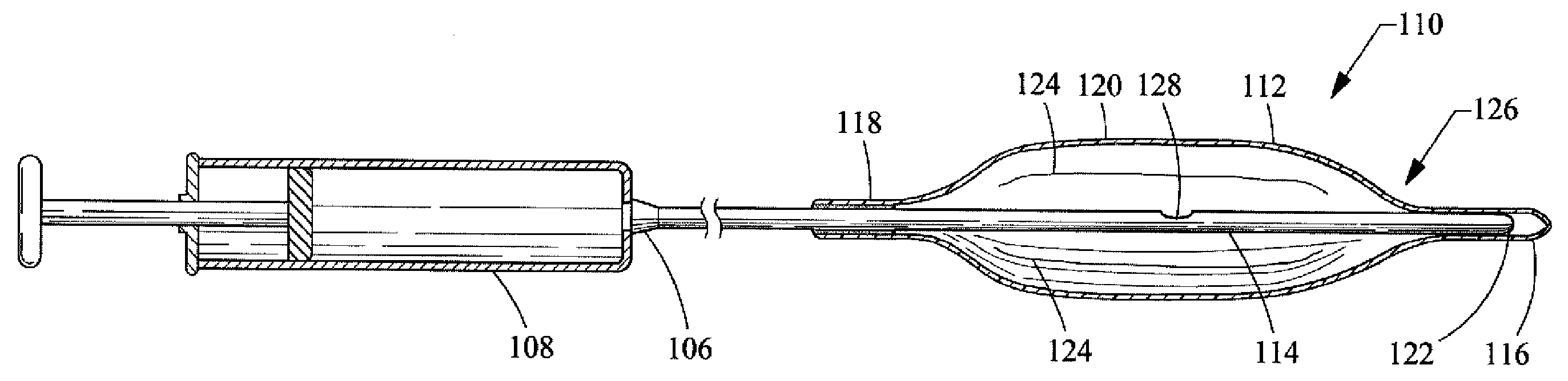
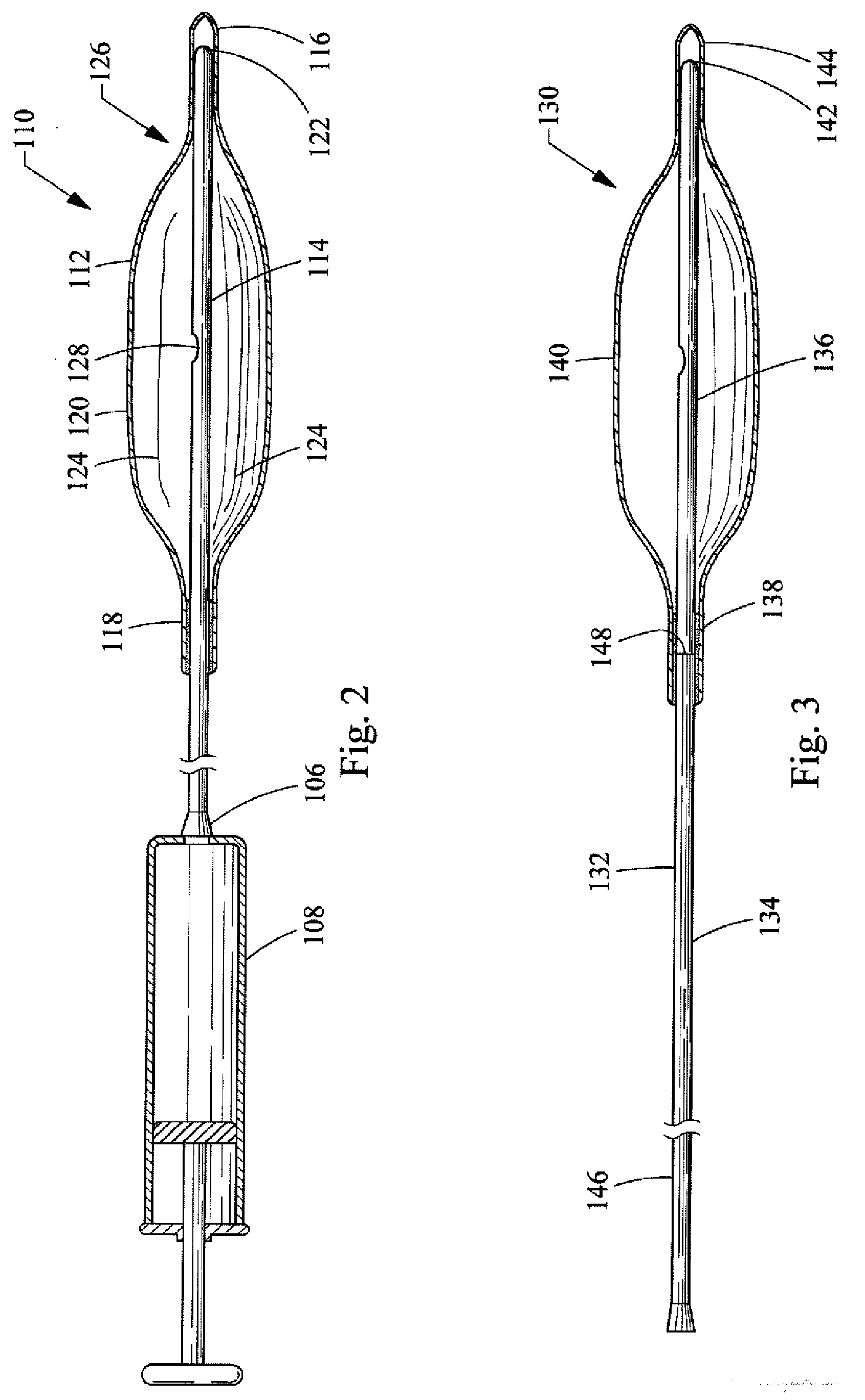
[0033]a balloon catheter 110 of the present invention is depicted in FIG. 2. The balloon catheter 110 includes a rounded, oval, cylindrical, bullet or other appropriately shaped balloon 112 that is affixed to a catheter 114. The balloon 112 is typically manufactured from a non-elastomeric material (e.g., a semi-rigid or non-compliant material), and preferably comprises a translucent, transparent or optically clear film. For example, the balloon 112 could be manufactured from a biocompatible polymer such as polyamide, polyurethane, polyester, polyolefin, polyethylene terephthalate and the like.

[0034]The balloon 112, as shown in the drawings, includes a distal end 116, a proximal end 118 and a central portion 120. However, different configurations or designs can also be utilized for the balloon 112. For example, the distal end 116 and the proximal end 118 could both comprise a tubular construction so as to form a neck. The balloon 112 is attached to the catheter 114 by inserting the d...

third embodiment

[0045]a balloon catheter 150 of the present invention is depicted in FIG. 4. The balloon catheter 150 of this embodiment is similar to the embodiment of the balloon catheter 130 shown in FIG. 3 in that it also comprises a two-part catheter 152 having a flexible portion 154 and a rigid portion 156. However, the rigid portion 156 does not extend to the distal end 164 of the balloon 160. In other words, the rigid portion 156 only extends from near the proximal end 158 of the balloon 160 to part way into the interior volume of the balloon 160, and the distal end 162 of the rigid portion 156 does not form a slip joint with the distal end 164 of the balloon 160.

[0046]With the exception of the two-part catheter 152 described above, and the length of the rigid portion 156 thereof, the remaining components of the balloon catheter 150 of the third embodiment are the same or similar to the components of the balloon catheter 130 of the second embodiment. A detailed description of these componen...

seventh embodiment

[0057]a balloon catheter 260 of the present invention is depicted in FIG. 8. The balloon catheter 260 of this embodiment comprises a flexible elongate outer catheter 262 that is fixedly connected at its distal end 264 to the proximal end 266 of the balloon 268. The proximal end 270 of outer catheter 262 includes a luer fitting 272 that is configured to attach to an inflation device such a standard medical syringe (as shown in FIG. 2). The outer catheter 262 has a construction similar to that described in connection with the above embodiments.

[0058]The balloon catheter 260 further comprises an elongate stiffening member 274 disposed within the lumen 276 of the outer catheter 262. The diameter or cross-sectional area of the stiffening member 274 is generally less than the diameter or cross-sectional area of the lumen 276 so as to allow the passage of fluid between the luer fitting 272 (i.e., the inflation device) and the interior of the balloon 268. In other words, the diameter of the...


PUM


Abstract

A balloon catheter including an inflatable balloon affixed to a catheter. The proximal end of the balloon is affixed to the distal end of the catheter so as to provide an air tight seal there between. A stiffening member extends distally of the distal end of the catheter and forms a slip joint connection with the distal end of the balloon to permit the distal end of the balloon to axially move or translate relative to the distal end of the catheter. The slip joint allows the axial length of balloon to change during inflation or deflation without transferring tensile or compressive forces between the balloon and the catheter, thereby preventing transverse creases from forming in the surface of the balloon and preventing the catheter from bowing. The stiffening member provides alignment and lateral support to the distal end of the balloon.

Description

CROSS-REFERENCE TO RELATED APPLICATIONS[0001]This application claims the benefit of U.S. Provisional Application Ser. No. 60 / 922,769, filed Apr. 10, 2007, entitled “Non-Buckling Balloon Catheter With Spring Loaded Flexible Tip”, the entire contents of which are incorporated by reference.TECHNICAL FIELD[0002]This invention relates to medical devices, and more particularly to balloon catheters that can be placed within a body lumen and inflated to perform various medical procedures. The invention is especially relevant to balloon catheters with balloons formed of non-elastomeric films or materials, wherein the film that forms the balloon is folded and unfolded during deflation and inflation, respectively, of the balloon.BACKGROUND OF THE INVENTION[0003]Balloon catheters are used to perform various medical procedures wherein the balloon is positioned within a body lumen or canal and subsequently inflated. In some of these medical procedures, such as in an angioplasty procedure, the bal...

Claims


Application Information

Patent Timeline
Patent Type & Authority Applications(United States)
IPC IPC(8): A61M25/10A61M25/18A61F2/958
CPCA61M25/10A61M25/1027A61M2025/1088A61N5/062
Inventor BROWN, HILBERT D.CHEN, STEVEN K.KENNEDY, II, KENNETH C.
Owner WILSONCOOK MEDICAL
Why Eureka
Try Eureka