Balloon folding control mechanism

a control mechanism and balloon technology, applied in the field of medical devices, can solve the problems of reducing the effectiveness of angioplasty procedures, reducing the cross-sectional area of the balloon, and pdt procedures that do not allow the expansion balloon b>12/b> to exert excess pressure, so as to reduce the cross-sectional area and eliminate the transverse creasing of the central portion of the balloon

Active Publication Date: 2009-01-22
COOK MEDICAL TECH LLC
View PDF14 Cites 34 Cited by
  • Summary
  • Abstract
  • Description
  • Claims
  • Application Information

AI Technical Summary

Benefits of technology

[0021]The slip joint connection allows the distal end of the balloon to axially move or translate with respect to the distal end of the catheter while maintaining axial alignment of the balloon relative to the stiffening member. This prevents the relative axial rigidity of the catheter and stiffening member from generating any axial tensile or compressive forces in the balloon. Consequently, transverse creasing of the central portion of the balloon is eliminated or at least minimized. The slip joint connection similarly prevents the balloon from generating any adverse forces in the catheter or stiffening member during inflation or deflation of the device. Thus, the catheter and stiffening member will not be bowed or stretched as result of the inflation or deflation of the balloon.
[0022]The slip joint balloon catheter of the present invention further includes a balloon folding control mechanism that is configured to promote refolding of the balloon into a predetermined and desired folding configuration upon deflation. In particular, the balloon folding control mechanism is configured to promote refolding of the balloon into at least a 3-wing configuration, thereby allowing the deflated balloon to assume a minimal cross-sectional area.

Problems solved by technology

As will be explained below, conventional balloon catheters have a number of shortcomings that make them inadequate for many of the above-described procedures, and in particular, for PDT procedures.
This may result in a decrease in effectiveness of the angioplasty procedure.
This is because typical PDT procedures do not allow the expanded balloon 12 to exert excess pressure or heavy contact on the interior surface of the body lumen.
Consequently, the device may be more difficult to maneuver during ingress or egress of the device through the body's canals.
In addition, the resulting “wrinkled” surface of the balloon 12 may cause irritation to body canal tissue during ingress or egress of the device and / or prevent the device from passing through the endoscope channel.
Although slip joint balloon catheters have overcome many of the disadvantages of conventional fixed length balloon catheters, slip joint balloon catheters may be difficult to refold into the pre-inflated folded state.
However, the balloon, and particularly a slip joint balloon, may not refold into the initial folded configuration.
This is most likely due to elongation and / or plastic deformation of the balloon during inflation.
This may make it difficult or impossible to remove the balloon from the patient, particularly if the balloon catheter was introduced into the patient through an endoscope or other elongate introducer.
The balloon may also get jammed in the endoscope upon withdrawal.
This is most likely due to the loss of “fold memory” in the balloon material as a result of the plastic deformation incurred by the inflation of the balloon.

Method used


Image

  • Balloon folding control mechanism
  • Balloon folding control mechanism
  • Balloon folding control mechanism

Examples


first embodiment

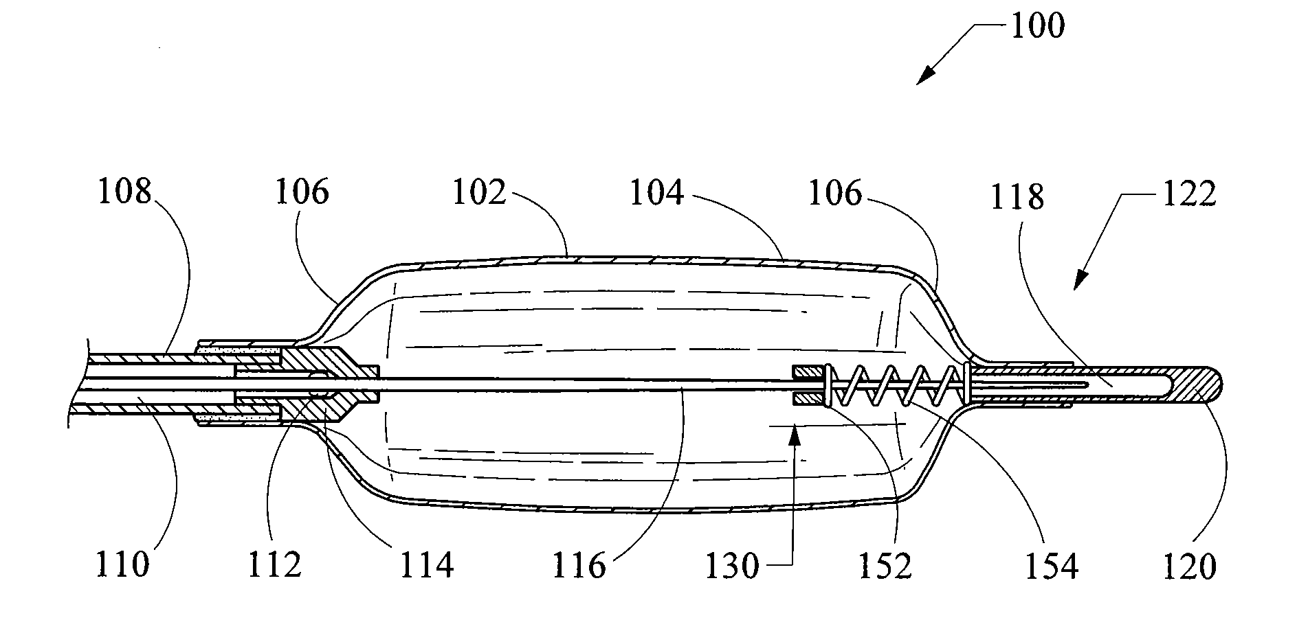
[0062]a balloon catheter 100 of the present invention is depicted in FIG. 19, which illustrates the distal portion (i.e., the balloon portion) of the balloon catheter 100. The balloon catheter 100 includes a balloon 102 having a cylindrical central element 104 and a pair of conical end elements 106. The balloon 102 is typically manufactured from a non-elastomeric material (e.g., a semi-rigid or non-compliant material), and preferably comprises a translucent, transparent or optically clear film. For example, the balloon 102 could be manufactured from a biocompatible polymer such as polyamide, polyurethane, polyester, polyolefin, polyethylene terephthalate and the like. The balloon 102 is generally manufactured as a unitary structure and in the shape of its 3-dimensional inflated stated.

[0063]The proximal end of the balloon 102 is fixedly connected to the distal end of a flexible elongate outer catheter 108. The proximal end of the outer catheter 108 includes a hub (not shown) that is...

second embodiment

[0071]FIG. 20 is a cross-sectional side view of the distal portion of the slip joint balloon catheter 100 of FIG. 19. However, this figure illustrates a balloon folding control mechanism 130 in accordance with the present invention. In this particular embodiment, the balloon folding control mechanism 130 comprises a stop collar 142 affixed to the stiffening member 116 at a specific distance X from the proximal face of the end cap 120. As explained above in connection with FIG. 19, the distance X represents the maximum amount of shortening that the balloon 102 will be allowed to undergo during deflation, and is selected based upon the aspect ratio of the balloon and the folding mode desired. For example, with respect to the balloon catheter 100 illustrated in FIGS. 19 and 20, the balloon 102 has an aspect ratio of about 1.8. With reference to FIG. 18, and assuming that a 3-wing folding configuration is desired, a slight amount of shortening is required such that the ratio S / D would b...

third embodiment

[0072]FIG. 21 is a cross-sectional side view of the distal portion of the slip joint balloon catheter 100 of FIG. 19. However, this figure illustrates a balloon folding control mechanism 130 in accordance with the present invention. In this particular embodiment, the balloon folding control mechanism 130 comprises a stop collar 152 in combination with a compression spring 154. The stop collar 152 is affixed to the stiffening member 116 and engages the proximal end of the spring 154. The spring 154 is positioned between the stop collar 152 and the proximal face of the end cap 120, and is configured to apply a biasing force therebetween. The position of the stop collar 152 and / or the length of the spring 154 may be selected to ensure that the spring 154 engages the end cap 120, or engages the end cap 120 at a specified force level, thereby inhibiting excessive shortening of the balloon 102. Because the spring 154 may be pre-loaded in compression, it is capable of lengthening and thus ...


PUM


Abstract

A balloon catheter including an inflatable balloon affixed to a catheter. The proximal end of the balloon is affixed to the distal end of the catheter so as to provide an air tight seal there between. A stiffening member extends distally of the distal end of the catheter and forms a slip joint connection with the distal end of the balloon to permit the distal end of the balloon to axially move or translate relative to the distal end of the catheter. The slip joint allows the axial length of balloon to change during inflation or deflation without transferring tensile or compressive forces between the balloon and the catheter. A balloon folding control mechanism is disposed about the portion of the stiffening member traversing the interior of the balloon, and is configured to promote refolding of the balloon into a predetermined and desired folding configuration upon deflation.

Description

CROSS-REFERENCE TO RELATED APPLICATIONS[0001]This application claims the benefit of U.S. Provisional Application Ser. No. 60 / 958,849, filed Jul. 9, 2007, entitled “Balloon Folding Control Mechanism”, the entire contents of which are incorporated by reference.TECHNICAL FIELD[0002]This invention relates to medical devices, and more particularly to balloon catheters that can be placed within a body lumen and inflated to perform various medical procedures. The invention is especially relevant to balloon catheters with balloons formed of non-elastomeric (semi-rigid) films or materials, wherein the film that forms the balloon is folded and unfolded during deflation and inflation, respectively, of the balloon.BACKGROUND OF THE INVENTION[0003]Balloon catheters are used to perform various medical procedures wherein the balloon is positioned within a body lumen or canal and subsequently inflated. In some of these medical procedures, such as in an angioplasty procedure, the balloon is inflated...

Claims


Application Information

Patent Timeline
Patent Type & Authority Applications(United States)
IPC IPC(8): A61M25/10A61F2/958
CPCA61M25/10A61M25/1027A61M25/1029A61M25/1038A61M2025/1093A61M2025/1047A61M2025/1068A61M2025/1084A61M2025/1004
Inventor KENNEDY, II, KENNETH C.CARTER, MATTHEW P.
Owner COOK MEDICAL TECH LLC
Why Eureka
Try Eureka