Slip joint with clamp

a technology of slip joint and clamp, which is applied in the direction of hose connection, cable termination, manufacturing tools, etc., can solve the problems of difficult to secure the pipe connection of waste line under sinks, wash basins, tubs, etc., and reduce the diameter of the collar, reduce the risk of being put, and the effect of high resistan

Inactive Publication Date: 2011-11-10
IRIZZARY ARMANDO +1
View PDF11 Cites 19 Cited by
  • Summary
  • Abstract
  • Description
  • Claims
  • Application Information

AI Technical Summary

Benefits of technology

[0009]The collar is then compressed by the clamping means, which reduces the diameter of the collar by bending it so as close the slot. Upon being compressed by the clamp, the collar grips the outer pipe more tightly, and radially compresses the sealing ring against the inner conduit pipe. The resulting assembly provides a strong, rigid joint between the inner and outer conduit pipes that is highly resistant to being put out of alignment. Tightening of the collar and activation of the clamping means can, in preferred embodiments, be accomplished by hand, without the use of tools. These preferred embodiments permit quick and easy installation and disassembly, even in tight and hard-to-see spaces.

Problems solved by technology

Secure pipe connections for waste lines under sinks, wash basins, tubs, and other appliances can be difficult to make, because the building's waste lines are in fixed positions within the walls, and the basin is often fixed in its position as well by surrounding cabinetry or tiling.
The pipes and fittings found in today's construction are often made of very thin metal, or even plastic, and these components are relatively fragile and easily deformed.
The thick rubber O-rings and gaskets of the past have in many cases been replaced by less compressible thin plastic rings and washers, which are less tolerant of poor alignment.
The pipes and fittings are subject to being battered and knocked out of alignment as heavy bottles, jugs, and other items are pushed into the under-sink area.
The resulting misalignment of the pipes, sleeves, and sealing rings causes the compression fittings to develop leaks.
Under-sink leaks can go undetected for some time, resulting in considerable damage to cabinetry, floors, and to whatever lies below.
There is little prospect for the return of sturdy but expensive metal pipes and fittings to the field.
In pedestal sinks, the compression fittings known in the art are difficult to install because there is little or no room for a wrench; a difficulty that is compounded by the fact that it is difficult to see the fittings at all when they are in place within the pedestal.

Method used


Image

  • Slip joint with clamp
  • Slip joint with clamp
  • Slip joint with clamp

Examples


Embodiment Construction

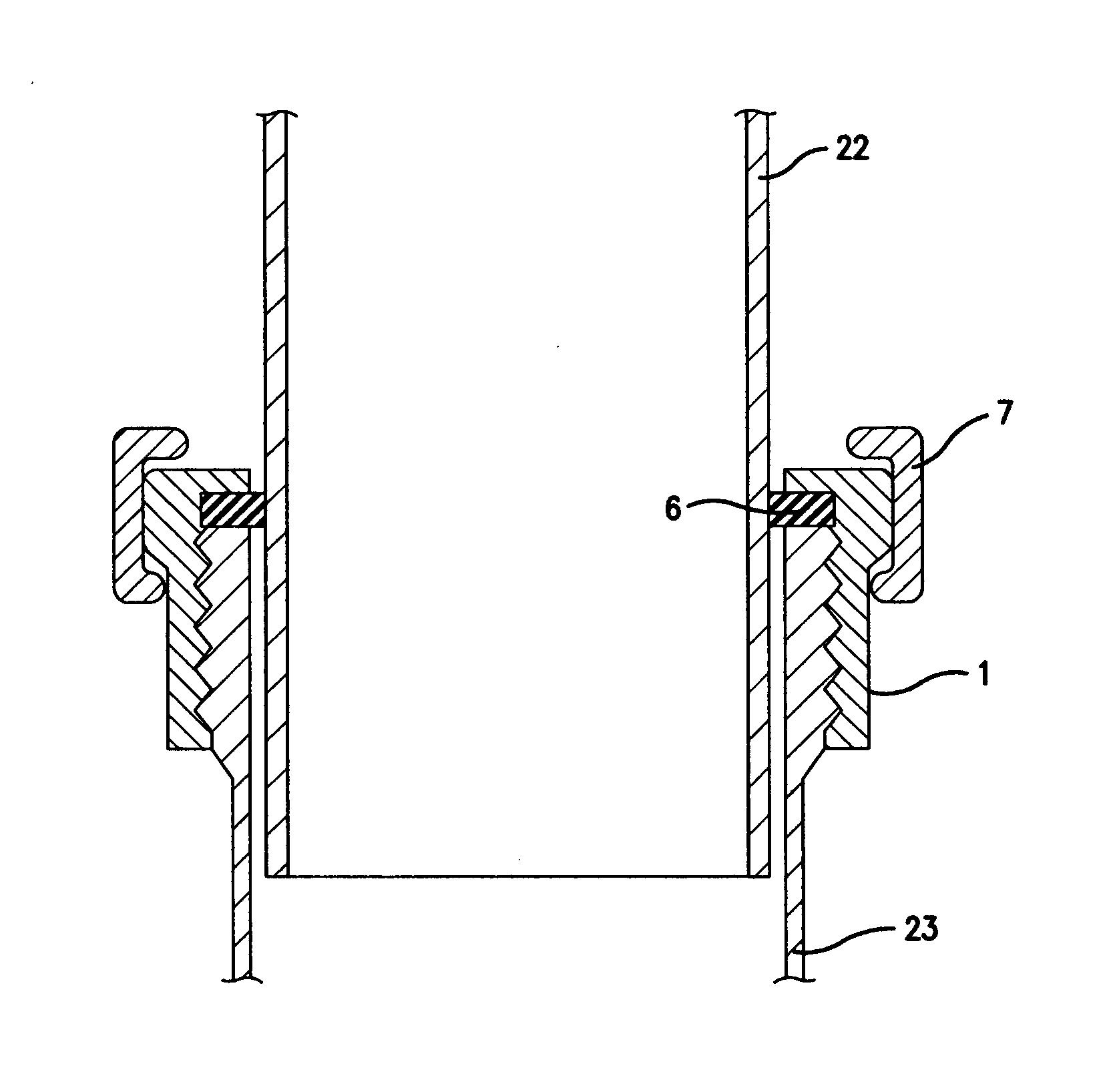
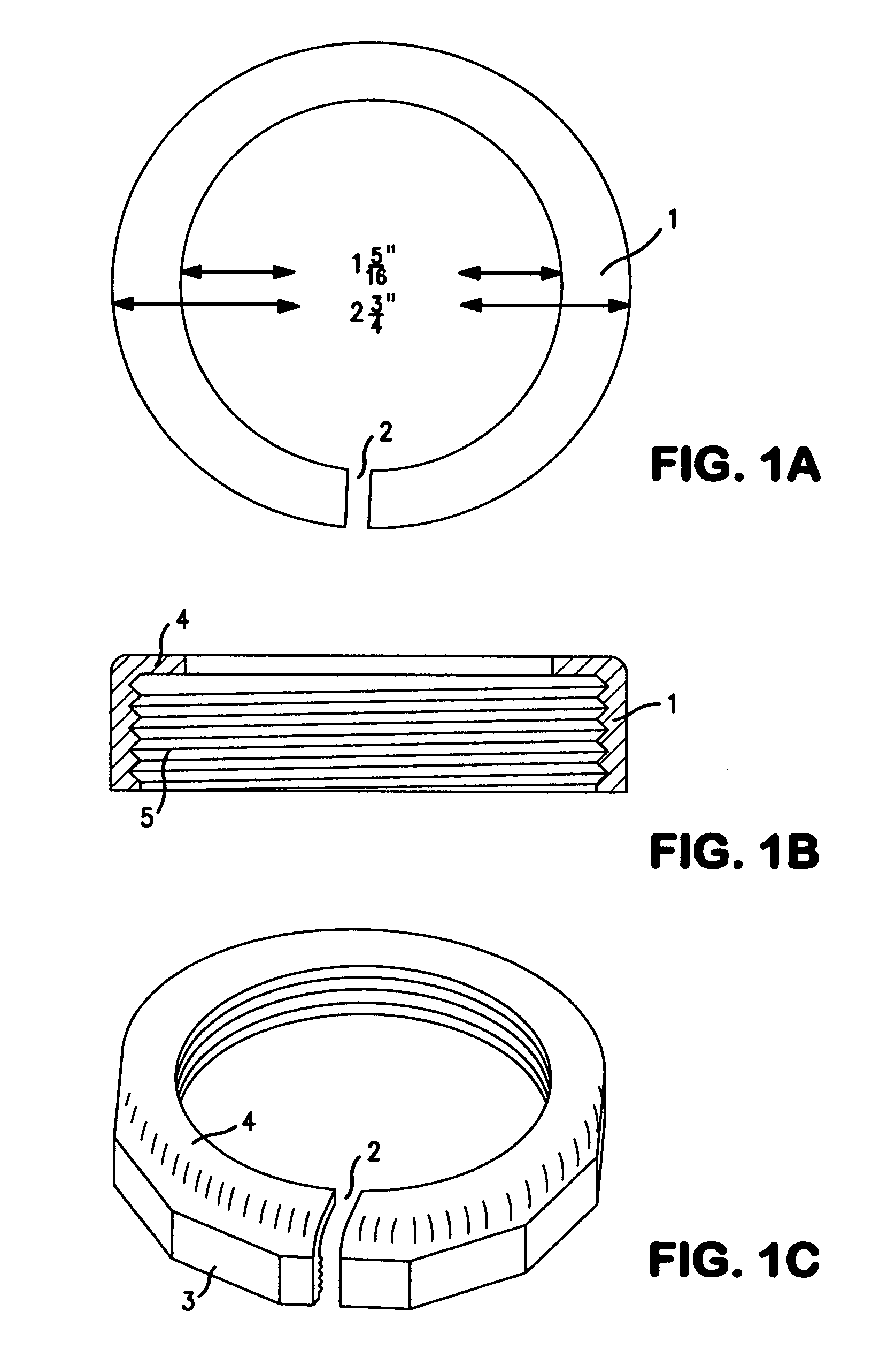
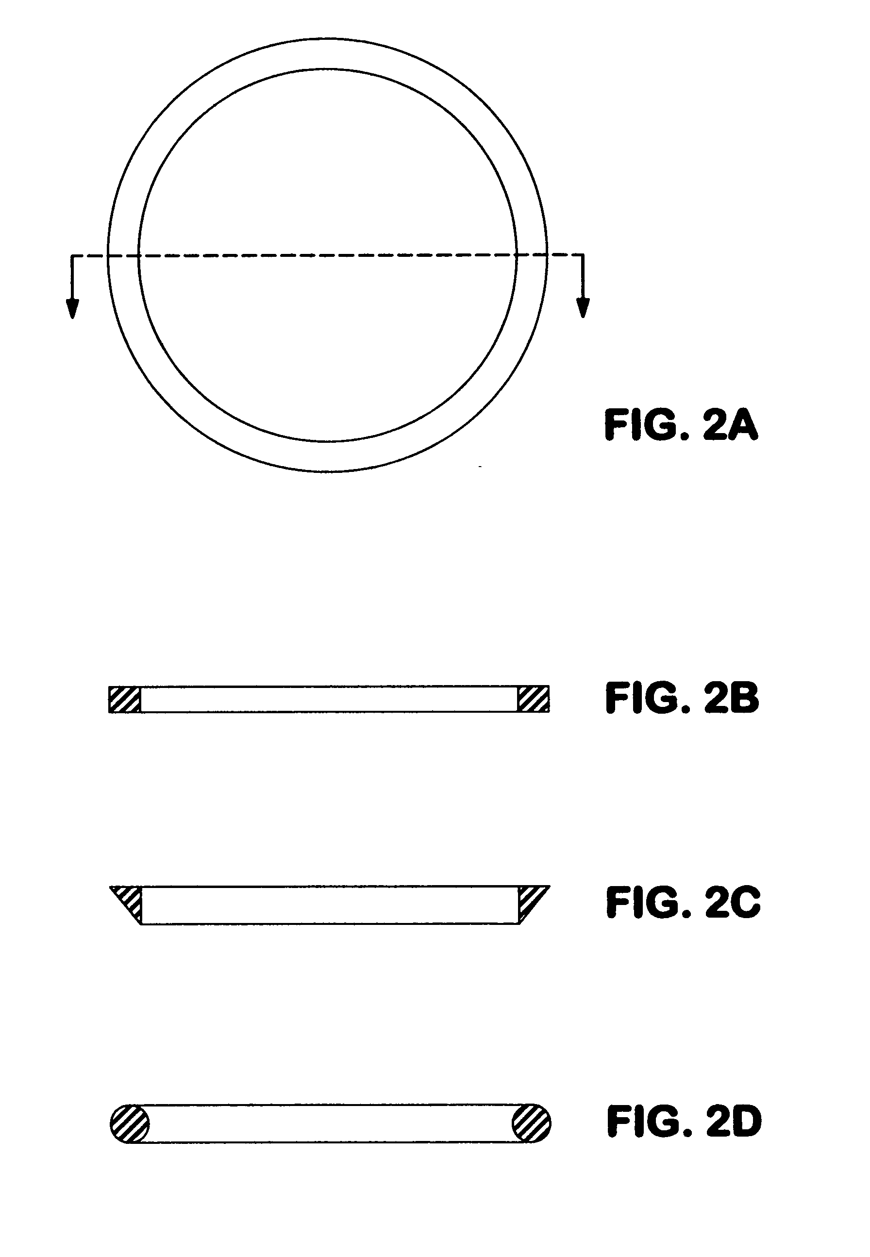
[0017]In a slip joint comprising an inner pipe telescopically associated with an outer pipe, and a compression fitting comprising a collar threaded onto the end of the outer pipe and a flexible sealing ring compressed by the collar against the outer pipe and forming a seal against the outer wall of the inner pipe, the invention provides an improvement which consists of a split collar, and a means for axially compressing said split collar.

[0018]The invention further provides a kit for preparing a compression fitting, comprising a split collar and a means for compression of said split collar. The invention further provides a method for sealing an inner pipe to an outer pipe in a slip joint, which comprises the steps of slipping a flexible sealing ring around the inner pipe, compressing said sealing ring against the end of said outer pipe by threading a split collar onto said end of said outer pipe, and compressing said split collar with a means for compression.

[0019]In a particular em...


PUM

PropertyMeasurementUnit
thicknessaaaaaaaaaa
flexibleaaaaaaaaaa
degrees of freedomaaaaaaaaaa

Abstract

The present invention provides an improved slip joint pipe coupling, which is reinforced by the mechanical compression of a split collar and sealing ring.

Description

RELATED APPLICATIONS[0001]This application claims priority of U.S. Provisional Application No. 61 / 342,278 filed on Apr. 11, 2010, the entire contents of which are incorporated herein by reference.FIELD OF THE INVENTION[0002]The invention relates to the field of pipe couplings, specifically to adjustable slip joint couplings.BACKGROUND OF THE INVENTION[0003]Secure pipe connections for waste lines under sinks, wash basins, tubs, and other appliances can be difficult to make, because the building's waste lines are in fixed positions within the walls, and the basin is often fixed in its position as well by surrounding cabinetry or tiling. The most widely accepted solution has been the use of slip joints, in which a pipe is allowed to telescope within a closely-fitting sleeve, which is usually an integral part of a fitting such as an elbow or trap. Regardless of the relative locations and orientations of the basin and waste line, two or three such telescoping fittings usually provide suf...

Claims


Application Information

Patent Timeline
Patent Type & Authority Applications(United States)
IPC IPC(8): F16L19/065F16L21/02B23P11/00F16L25/00
CPCF16L21/03F16L21/065F16L21/06
Inventor IRIZZARY, ARMANDOVINCENZI, JOHN C.
Owner IRIZZARY ARMANDO
Why Eureka
Try Eureka