Oil pressure control device for automatic transmission

a technology of oil pressure control and automatic transmission, which is applied in the direction of mechanical actuator clutches, mechanical apparatus, clutches, etc., can solve the problems of increasing the difficulty of transmission, increasing the difficulty of vehicle forward travel, and increasing the difficulty of vehicle driving, so as to simplify the structure of the switching valv

Inactive Publication Date: 2007-08-21
DENSO CORP
View PDF3 Cites 4 Cited by
  • Summary
  • Abstract
  • Description
  • Claims
  • Application Information

AI Technical Summary

Benefits of technology

[0012]According to another feature of the present invention, the switching valve comprises a spool which is movably supported in a casing of the switching valve. The spool is axially moved by a pressure difference between the modulated pressures from the first and second pressure modulating valves, to connect one of the pressure modulating valves with the oil pressure control valves, and disconnect the oil pressure control valves from the other pressure modulating valve. As above, the switching valve switches over the communication between the pressure modulating valves and the oil pressure control valves, due to the pressure difference, the structure of the switching valve becomes simpler.
[0013]According to a further feature of the present invention, a switching valve comprises a ball member movably supported in a switching chamber, and the ball member is moved therein by the pressure difference between the pressures from the pressure modulating valves, to close one of inlet openings of the switching chamber, the oil pressure at which is lower than that at the other inlet opening. This makes it also possible to make the switching valve in a simpler structure.

Problems solved by technology

It has become, however, more difficult to supply, by a single pressure modulating valve, a sufficient amount of working oil with a sufficiently high oil pressure to the increased number of the oil pressure control valves.
As above, in the prior art automatic transmission, the forward travel of the vehicle in case of the failure of the pressure modulating valves is limited to the vehicle travel with the limited gear change positions of automatic transmission.
Accordingly, it is difficult to drive the vehicle when a load to the vehicle travel is high, for example at a high speed and / or on an up-hill road.

Method used


Image

  • Oil pressure control device for automatic transmission
  • Oil pressure control device for automatic transmission
  • Oil pressure control device for automatic transmission

Examples


first embodiment

[0022]An embodiment of an oil pressure control device according to the present invention is explained with reference to the drawings.

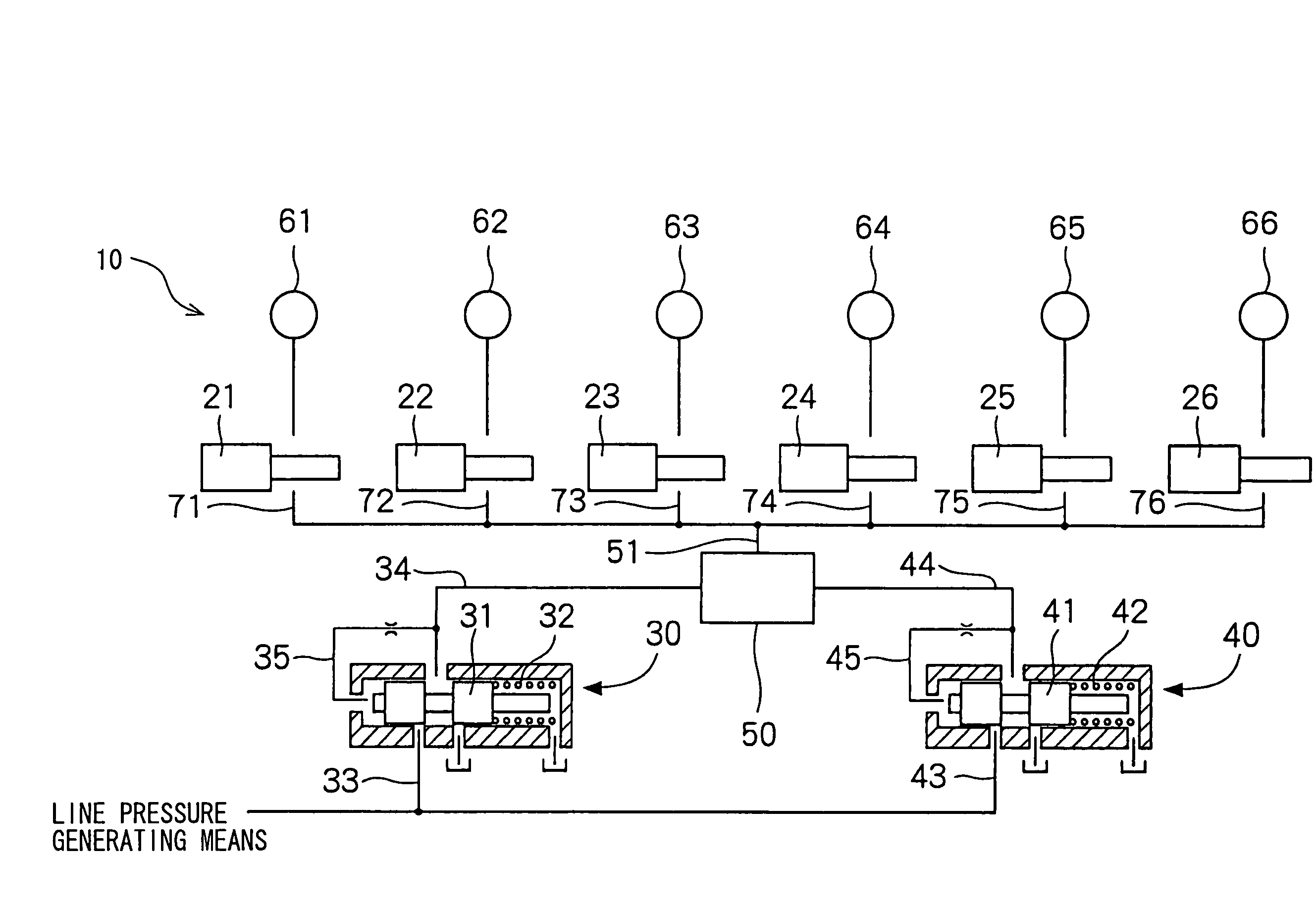
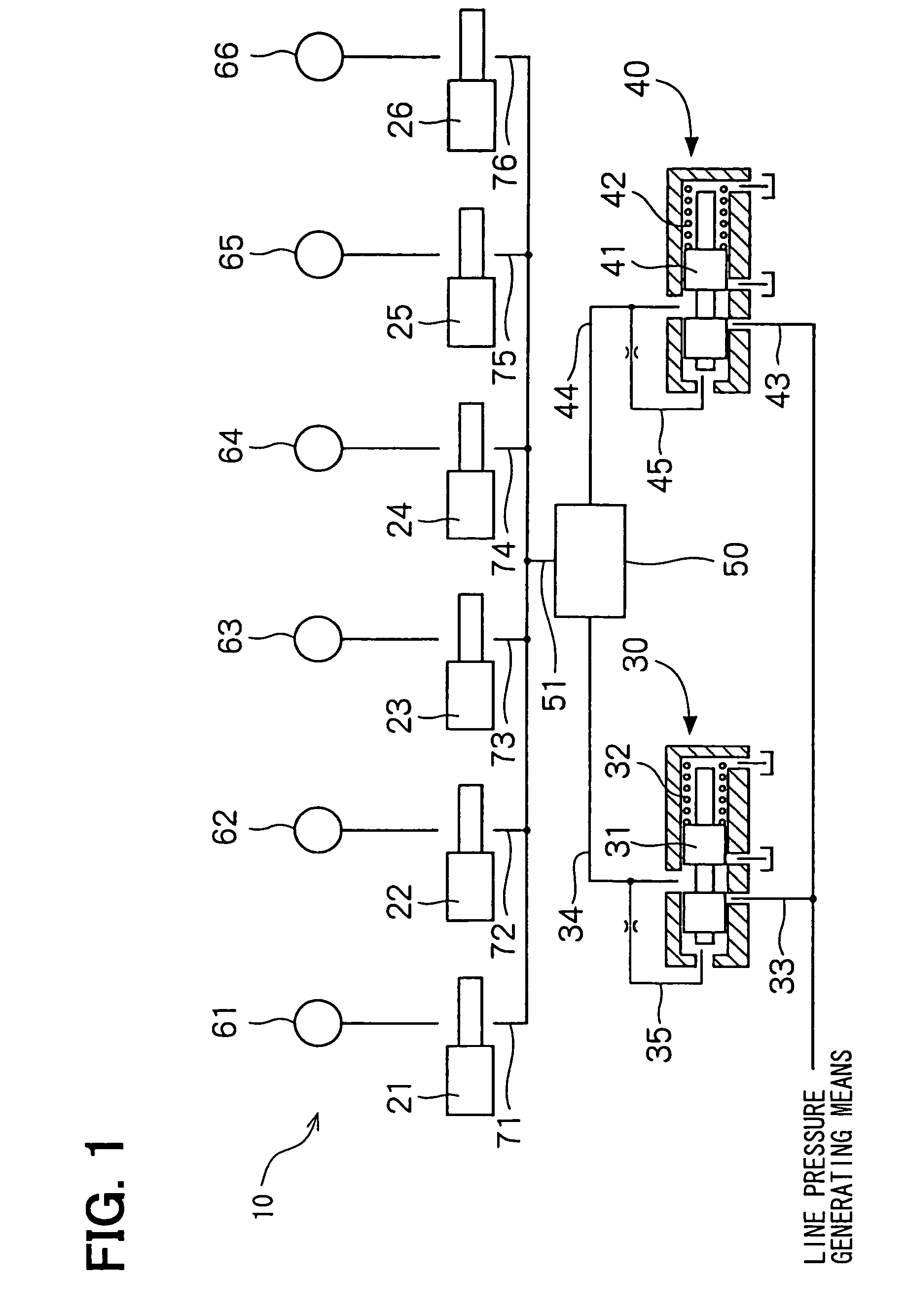
[0023]A first embodiment of the present invention is shown in FIG. 1. An oil pressure control device 10 for an automatic transmission of a motor vehicle comprises multiple (six) electromagnetic oil pressure control valves 21 to 26 respectively connected to friction engagement elements 61 to 66 (such as clutches and brakes), multiple (first and second) pressure modulating valves 30 and 40 respectively acting as a pressure decreasing valve, and a switching valve 50.

[0024]The electromagnetic oil pressure control valves 21 to 26 are connected to the friction engagement elements 61 to 66, as described above, to control oil pressure to be applied to the respective friction engagement elements 61 to 66, so that engagement or disengagement of the elements 61 to 66 is controlled. The electromagnetic oil pressure control valves 21 to 26 are respectively driven b...

second embodiment

[0037]A switching valve of the oil pressure control device according to a second embodiment is shown in FIG. 5. In the drawing, the same portions to the first embodiment are designated by the same reference numerals.

[0038]The second embodiment differs from the first embodiment in the structure of the switching valve. A switching valve 80 of the second embodiment comprises a ball member 81, as shown in FIG. 5. The switching valve 80 further has a switching chamber 83, which is formed in a casing 82. Openings 84 and 85, which are respectively connected to the first and second pressure modulating valves 30 and 40 through the oil pressure passages 34 and 44, are formed in the switching chamber 83. The oil pressure supply passage 51 is also connected to the switching chamber 83, so that the oil pressure from the first and / or second pressure modulating valves is connected to the oil pressure supply passage 51 through the switching chamber 83.

[0039]In the second embodiment, when one of the...


PUM


Abstract

In an automatic transmission having multiple oil pressure control valves for controlling friction engagement elements, a first and second pressure modulating valves are provided between an oil pressure generating means (pump) and the oil pressure control valves. A switching valve is further provided between the pressure modulating valves and the oil pressure control valves. In case that one of the pressure modulating valves becomes out of order, the oil pressure of a working oil is supplied to the oil pressure control valves from the other pressure modulating valve, so that the automatic transmission can be continuously operated even in the case that one of the pressure modulating valves becomes out of order.

Description

CROSS REFERENCE TO RELATED APPLICATION[0001]This application is based on Japanese Patent Application No. 2004-226819, which is filed on Aug. 3, 2004, the disclosure of which is incorporated herein by reference.[0002]1. Field of the Invention[0003]The present invention relates to an oil pressure control device for an automatic transmission of a motor vehicle.[0004]2. Background of the Invention[0005]In a recent automatic transmission for a motor vehicle, a number of multiple-stage gear changes is increased, and a number of electromagnetic oil pressure control valves for controlling oil pressure to be supplied to respective friction engagement elements (such as, clutches and brakes in the transmission device) is correspondingly increased. A pressure modulating valve is generally provided in fluid passages connecting an oil pressure generating means (such as a pump) with the oil pressure control valves, so that an original oil pressure from the pump is modulated (decreased) and supplie...

Claims


Application Information

Patent Timeline
Patent Type & Authority Patents(United States)
IPC IPC(8): F16H61/00
CPCF16H61/0021F16H61/12Y10T477/6936F16H2061/1264F16H2061/122
Inventor TAKAGI, AKIRA
Owner DENSO CORP
Why Eureka
Try Eureka