
Increasing cargo loading of vehicles

Inactive Publication Date: 2007-08-21
THE GOVERNMENT OF THE US SEC THE AIR FORCE
View PDF10 Cites 11 Cited by
  • Summary
  • Abstract
  • Description
  • Claims
  • Application Information

AI Technical Summary

Benefits of technology

[0009]Broadly, the invention provides an improved cargo airlifting system, in which the cargo carrying capability of an aircraft is increased by more effectively using the cargo space thereof.
[0014]Per the present invention, loaded standard pallets are stacked “bunk bed” style together on at least two levels to, e.g., effectively double the amount of equipment that can be transported in the same cargo-carrying aircraft.
[0018]Thus, employing standard pallets and a fork lift, a straight-forward drive-on, drive-off system can load two levels of equipment onto airlifters (e.g., C-5, C-17, C-141, and C-130) on the bi-level pallet assembly embodiment of the invention, to greatly reduce the number of transport aircraft required to deploy a desired amount of equipment.
[0019]The savings on such multi-level pallet loading in a cargo aircraft can be considerable. For example, for a C-17 aircraft the cost of one level loading is over $7,000 per pallet position or footprint. Such an aircraft with 18 pallet positions can cost over $136,000 each way or over $272,000 round trip, thus the above inventive system, utilizing two pallet levels, can save up to $272,000 for each deployment.
[0020]Accordingly, the multi level pallet assembly of the invention can more effectively utilize its deployment footprint in an airlifter by using the normally unused cargo space above the cargo secured to the floor of the aircraft. Thus the inventive system can free up more cargo aircraft to meet other demands, while saving millions of dollars over traditional deployment costs. The inventive concept applies to commercial as well as military aircraft.

Problems solved by technology

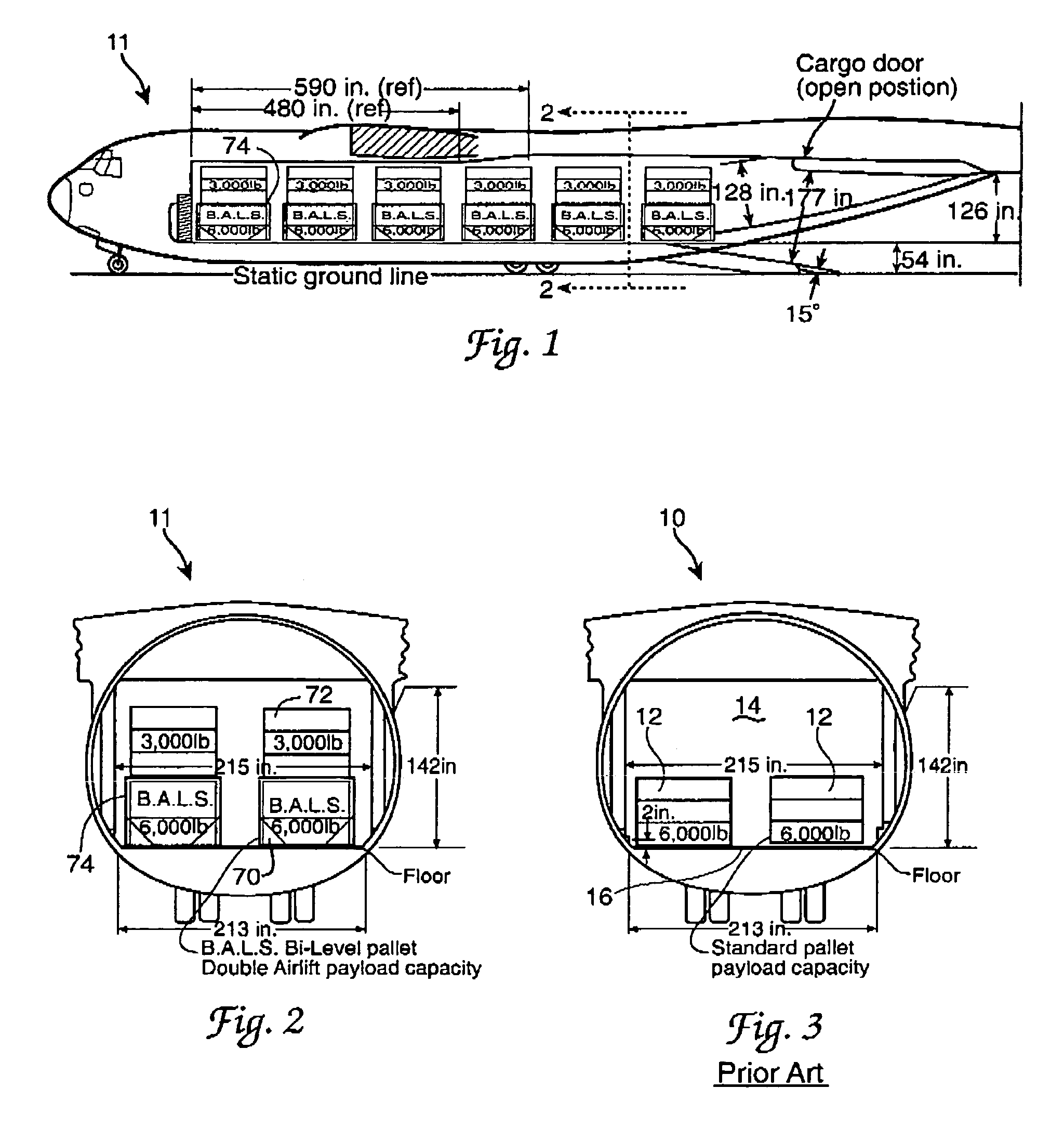
The current cargo aircraft design limits the amount of cargo an air lifter can carry because there is presently no way to utilize the ‘unused’ space above the cargo secured to the aircraft floor during transport (for a C-17 this ‘unused’ space equates to over 32,000 cu ft).

Method used


Image

  • Increasing cargo loading of vehicles
  • Increasing cargo loading of vehicles
  • Increasing cargo loading of vehicles

Examples


Embodiment Construction

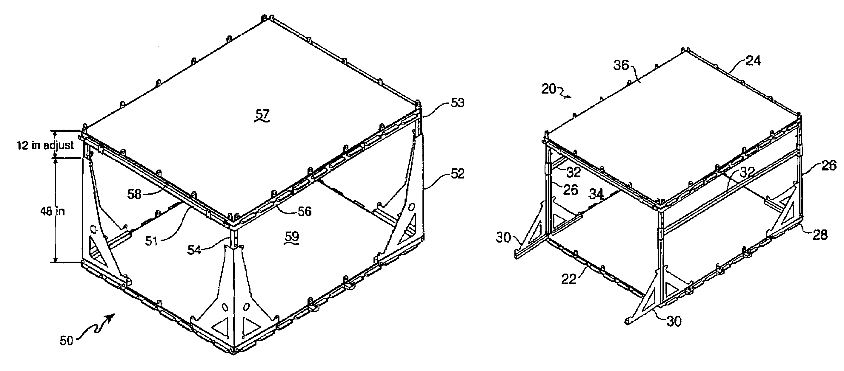
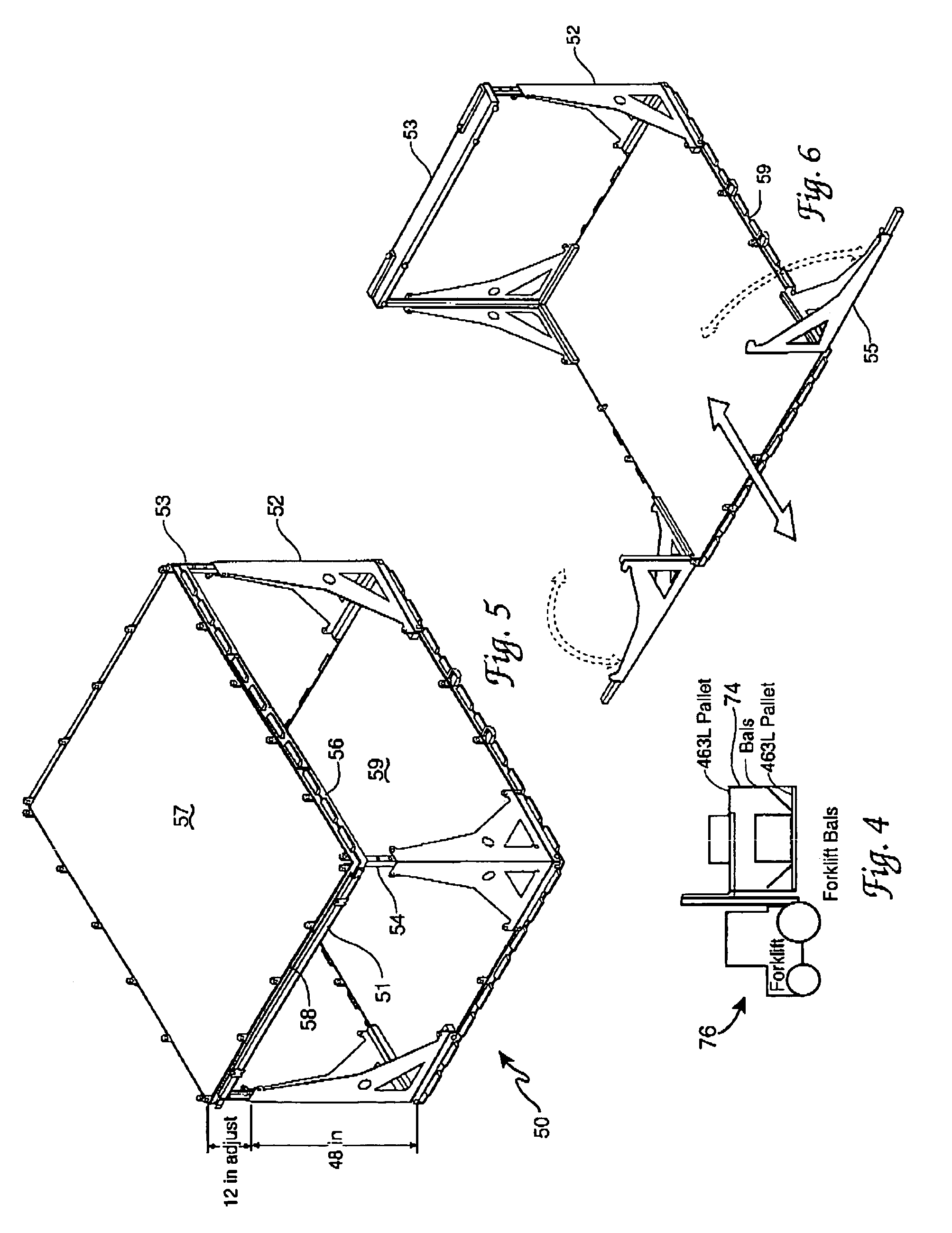
[0033]Referring now to the drawings, the standard way of airlifting cargo 12 is to load same on an aircraft 10, such as a C-17, e.g., by a fork lift, on one level, the aircraft floor 16, leaving considerable unused space 14 above the cargo 12, as shown or indicated in FIG. 3.

[0034]Since in a C-17 such unused space equates to over 32,000 cubic feet, the bi-level pallet assembly of the invention was devised to more effectively use such space and to potentially double the amount of cargo that can be transported in a C-17 or other aircraft. One embodiment 20 of the bi-level pallet assembly of the invention 20 is shown in FIG. 7, having a pair of pallets 22 and 24 separated by posts 26, which are braced by corner supports 28 and 30, with further support provided by cross bars 32 and pallet edge bars 34 and 36 for pallet 24, with similar bars (not shown) for pallet 22 around its periphery, as shown or indicated in FIG. 7. The pallet edge bars can engage tabs on an aircraft floor to anchor...


PUM


Abstract

Provided is a bi-level pallet assembly wherein a pallet is mounted over another on posts supported by corner braces or on posts supported by panels therebetween so that the two pallets are married bunk-bed style together. Cargo is stored on each of the upper and lower pallets and driven by a forklift onto a cargo aircraft to double the normal cargo carrying capacity of such aircraft by utilizing formerly unused space above the first level of cargo. The bi-level pallet assembly of the invention can potentially double the cargo capacity of such aircraft and free up cargo aircraft to meet other demands with a considerable savings of dollars over traditional deployment costs.

Description

STATEMENT OF GOVERNMENT INTEREST[0001]The invention described herein may be manufactured and used by or for the Government for governmental purposes without the payment of any royalty thereon.RELATED APPLICATIONS[0002]NoneFIELD OF THE INVENTION[0003]This invention relates to increasing the cargo capacity of vehicles, particularly aircraft.BACKGROUND OF THE INVENTION[0004]The current cargo aircraft design limits the amount of cargo an air lifter can carry because there is presently no way to utilize the ‘unused’ space above the cargo secured to the aircraft floor during transport (for a C-17 this ‘unused’ space equates to over 32,000 cu ft).[0005]The cargo is typically loaded on standard 463 L cargo pallets in the C-17 and the loaded pallets occupy only about 8,222 cu ft for about 18 pallet positions. If more pallets could be loaded into the C-17, the cargo carrying ability of such aircraft would be dramatically increased within its airlifting capability and the number of such aircra...

Claims


Application Information

Patent Timeline
IPC IPC(8): B65D19/00B65D19/38
CPCB65D88/129B65D88/14B65D88/522
Inventor WERTZ, ROBERT O.VATCHER, CHARLES A.MANN, CHARLES M.KALTENTHALER, UDO
Owner THE GOVERNMENT OF THE US SEC THE AIR FORCE
Learn More