Landing gear assembly for a trailer

a technology for landing gear and trailers, which is applied in the direction of loading/unloading vehicles, vehicle maintenance, transportation items, etc., can solve the problems of only extending and retracting the legs in high and low gears from the master leg location, affecting the height of the trailer above the ground, and affecting the service life of the landing gear assembly

Inactive Publication Date: 2007-08-21
BAXTER PROPERTIES
View PDF16 Cites 26 Cited by
  • Summary
  • Abstract
  • Description
  • Claims
  • Application Information

AI Technical Summary

Benefits of technology

[0005]The present invention solves these problems, providing a new landing gear assembly that eliminates the master and slave arrangement of the previous landing gear assemblies and allows operation of the assembly from either side of the trailer. In addition, the modular nature of the new landing gear assembly allows a single configuration to be used in both legs by changing the location of the mounting plate. In addition, a set of legs may be mounted in any configuration required by the different types of trailers.

Problems solved by technology

Loading the trailer or placing the landing gear assembly in contact with relatively soft ground may affect the trailer height above the ground.
As a result, relatively large forces are placed on the lifting mechanism in each leg and the cross bar between the two legs which affects the service life of the landing gear assembly.
Another drawback of current landing gear assemblies is that the operator can only extend and retract the legs in high and low gears from the master leg location.
Still another limitation of current landing gear assemblies is that a single set of legs cannot be mounted in the multiple configurations required by the different types of trailers.

Method used


Image

  • Landing gear assembly for a trailer
  • Landing gear assembly for a trailer
  • Landing gear assembly for a trailer

Examples


Embodiment Construction

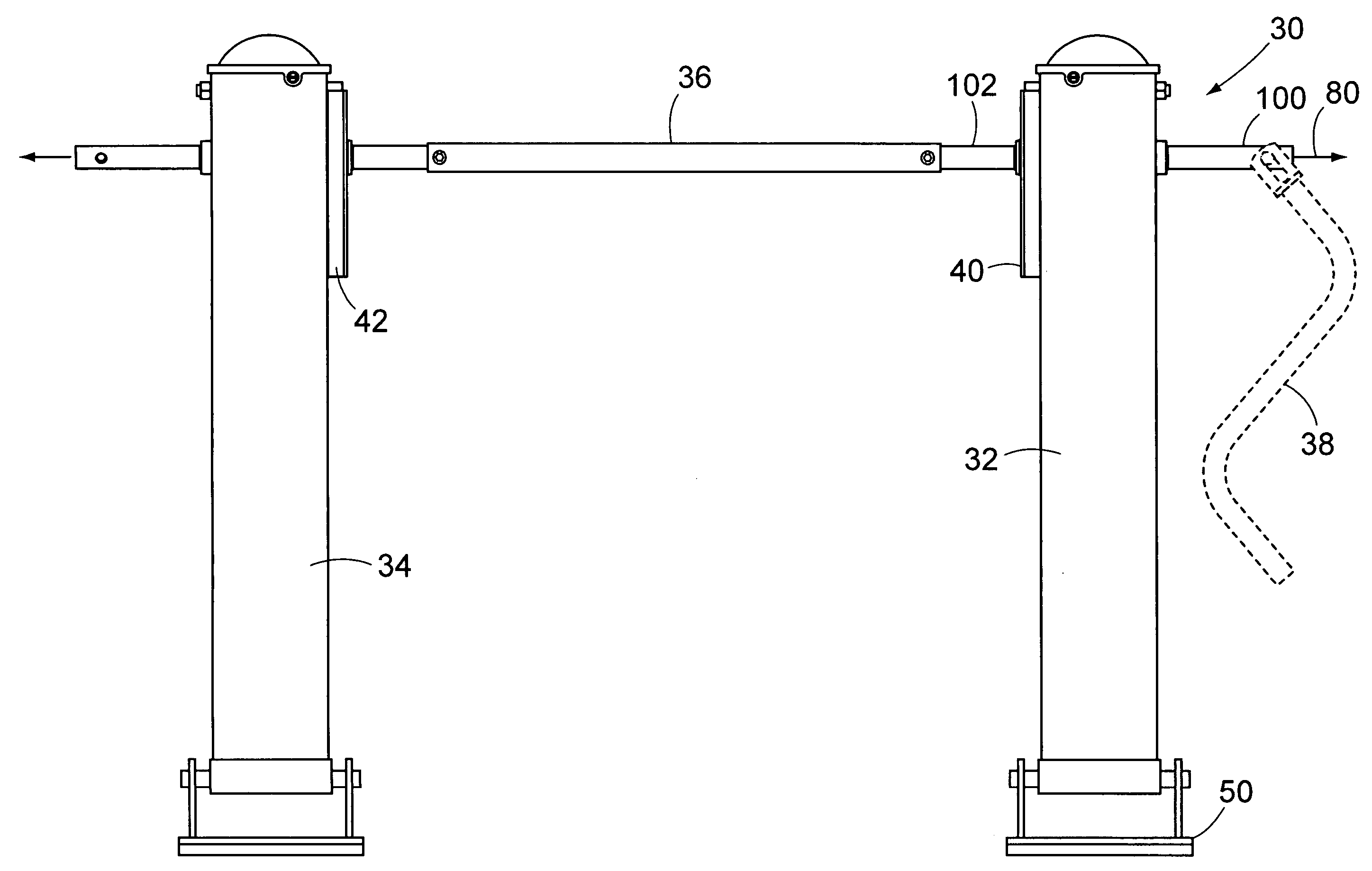
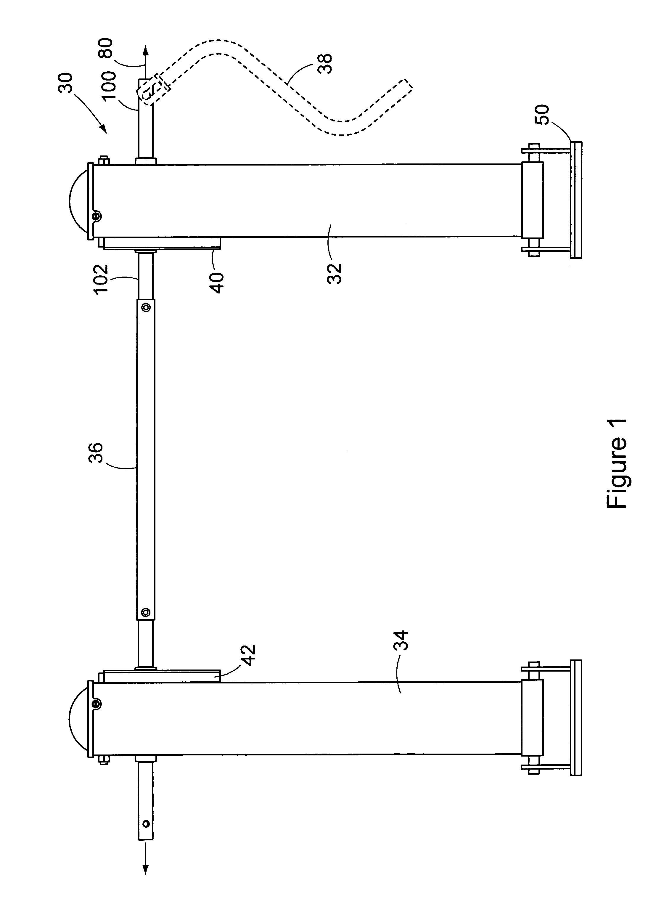
[0027]Referring now to the drawings, and more particularly to FIG. 1 a front plan view of a landing gear assembly is shown generally at 30. The landing gear assembly comprises a first leg 32, a second leg 34, and a connecting member 36. In the embodiment shown, the connecting member is a connecting shaft that is cylindrical. The first and second legs are configured to selectively extend and retract in length. A crank 38 may by attached to the landing gear assembly and operated to extend and retract the legs. The first leg 32 includes a first mounting plate 40 and the second leg 34 includes a second mounting plate 42. As will be discussed in more detail below, the relative location of a mounting plate on a leg is the only structural difference between the first and second legs of a landing gear assembly. The mounting plates allow the legs to attach to a trailer in a known manner.

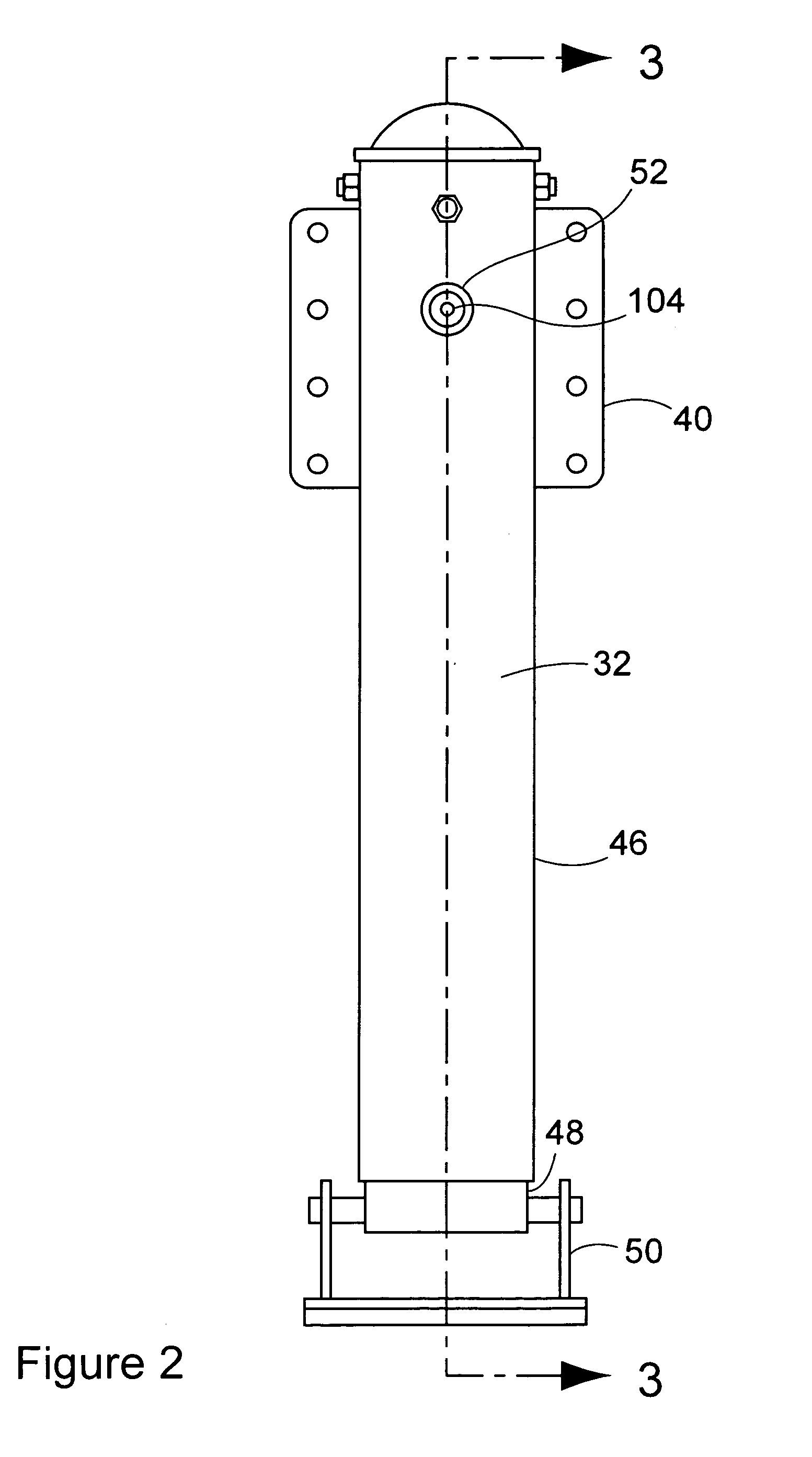
[0028]Referring now to FIGS. 2 and 3, FIG. 2 shows a side plan view of the first leg 32 of the landing gea...


PUM


Abstract

A landing gear assembly for supporting a trailer. The landing gear assembly having first and second legs and a connecting member. Each leg is configured to selectively extend and retract in length. The connecting member operatively connects the first and second legs and is rotatable about an axis relative to the trailer and is axially movable between a first position and a second position. The first and second legs are each configured to extend in length a first amount per revolution of the connecting member about the axis of the connecting member when the connecting member is in the first position. The first and second legs are each configured to extend in length a second amount per revolution of the connecting member about the axis of the connecting member when the connecting member is in the second position. The first amount is greater than the second amount.

Description

FIELD OF THE INVENTION[0001]The present invention generally is directed to an apparatus for supporting the front end of a trailer that has been detached from a truck, and more particularly to a landing gear assembly.BACKGROUND OF THE INVENTION[0002]One of the primary modes of shipping goods is by a truck pulled trailer. These trailers are equipped with a landing gear assembly that is retracted in a stored position above the ground while the trailer is coupled to the truck. The landing gear assembly allows the trailer to be uncoupled from the truck when necessary. After placing the trailer in a desired location, the operator lowers the landing gear assembly into contact with the ground. Once in contact with the ground, the truck is disengaged from the trailer. Loading the trailer or placing the landing gear assembly in contact with relatively soft ground may affect the trailer height above the ground. When the operator is ready to re-couple the trailer to a truck it may be necessary ...

Claims


Application Information

Patent Timeline
Patent Type & Authority Patents(United States)
IPC IPC(8): B60S9/02B60P1/00B60S9/00
CPCB60S9/08
Inventor BAXTER, BOBBY G.
Owner BAXTER PROPERTIES
Why Eureka
Try Eureka