Systems for providing controlled power to ultrasonic welding probes

a technology of ultrasonic welding probes and control systems, which is applied in the direction of feeding apparatus, vibration measurement in solids, electron beam welding apparatus, etc., can solve the problems of limiting the adjustable control methods that can be incorporated into the design, the power density of the packaged system is relatively low, and the optional system features cannot be easily upgraded in the field. , to achieve the effect of safe reduction of the output amplitude of an ultrasonic generator, extending the service life of various components,

Active Publication Date: 2009-01-13
DUKANE IAS LLC
View PDF15 Cites 25 Cited by
  • Summary
  • Abstract
  • Description
  • Claims
  • Application Information

AI Technical Summary

Benefits of technology

[0008]According to yet another embodiment of the present invention, a method for testing the power of an ultrasonic generator includes transmitting a test signal to an input module for testing an incoming power supply. In response to a positive test result, transmitting a test signal to a plurality of buses for testing an internal power supply. In response to a positive test result from the internal power supply, a test signal is transmitted to an outputting power supply. In response to a positive test result from the outputting power supply, full operation of the ultrasonic generator is allowed.
[0011]According to yet another embodiment of the present invention, a method of preventing an overload trip of an ultrasonic generator is provided and includes sampling a power level of the ultrasonic generator. It is then determined whether the sampled power is within a set percentage of an overload trip level. In response to the sampled power being within the set percentage of the overload trip level, an amplitude of the sampled power is decreased.
[0013]According to another embodiment of the present invention, a method for safely decreasing the output amplitude of an ultrasonic generator includes activating a ramp down amplitude control algorithm in the ultrasonic generator and gradually reducing the output amplitude of the ultrasonic generator over a predetermined period of time. This method allows to extend the service life of various components of an ultrasonic stack, such as sonotrodes (horns), boosters and transducers, by reducing stresses introduced at the end of a cycle when the amplitude is turned off abruptly.

Problems solved by technology

In many of these current ultrasonic generators, most of the designs use architectures and packaging methods that are not easily assembled and serviced, or the optional system features can not be easily upgraded in the field.
Also, by utilizing conventional design methods, the power density of the packaged system is relatively low.
Most of the current ultrasonic generators also use analog components, which limit the adjustable control methods that can be incorporated into the design.
Also, by utilizing mostly analog components in the design, the ultrasonic generator will incorporate more circuitry, have a greater sensitivity to noise and will require a larger amount of circuit board component space.

Method used


Image

  • Systems for providing controlled power to ultrasonic welding probes
  • Systems for providing controlled power to ultrasonic welding probes
  • Systems for providing controlled power to ultrasonic welding probes

Examples


Embodiment Construction

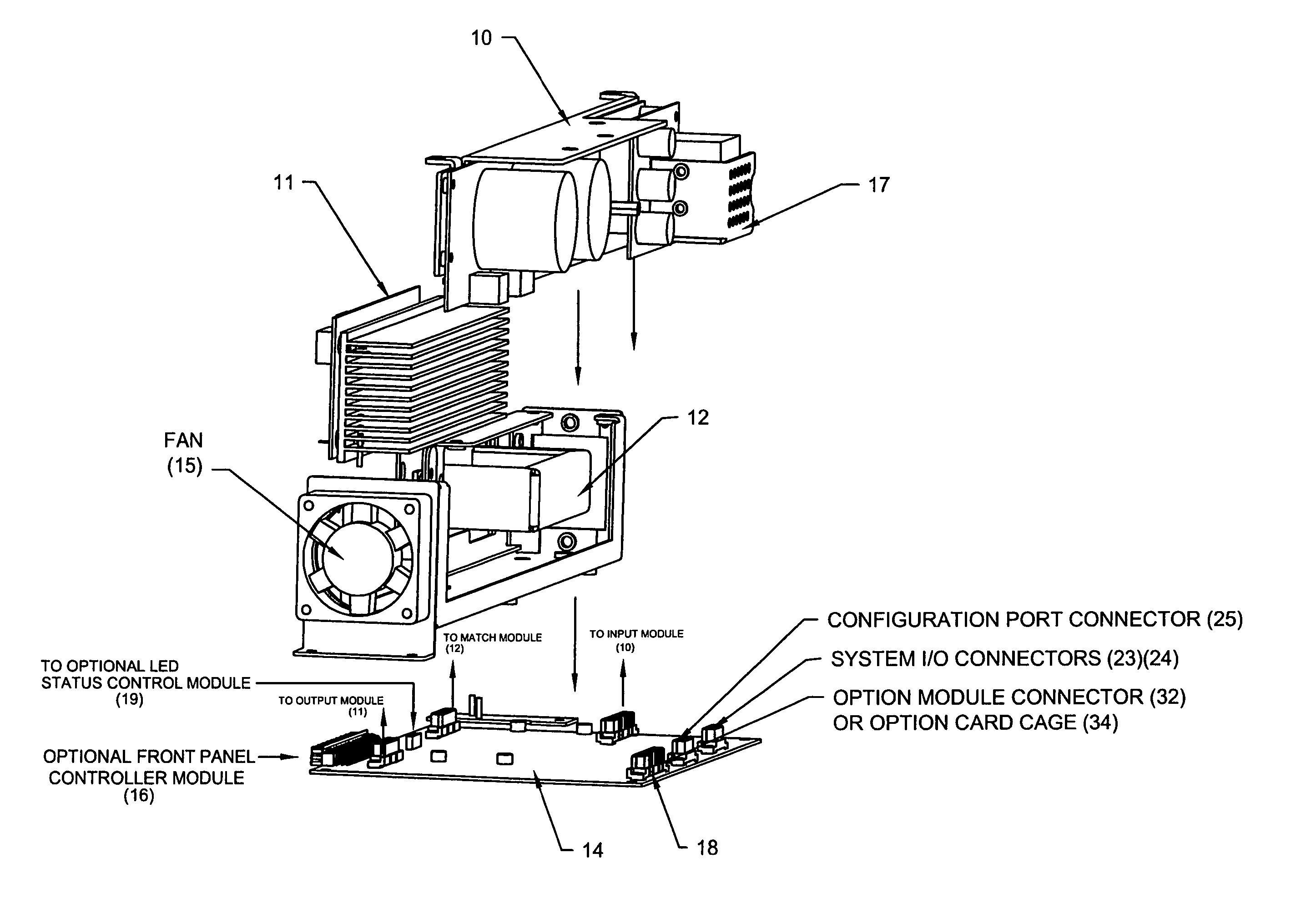
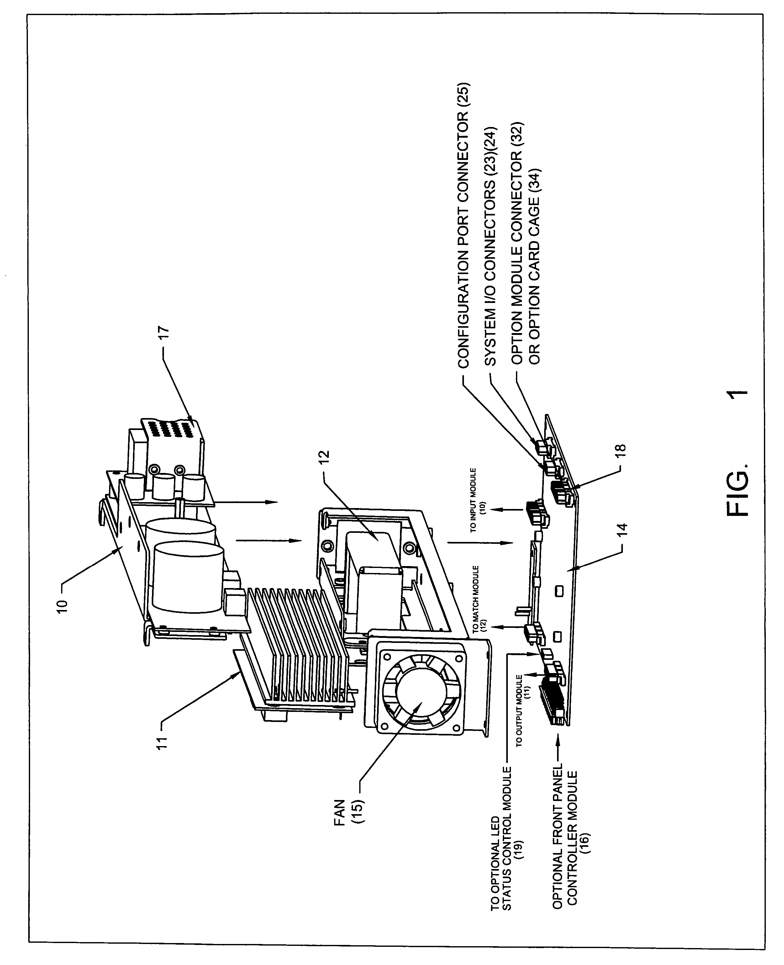
[0036]FIG. 1 illustrates the modular system architecture of a basic ultrasonic power supply in which the core system components are an Input Module 10, an Output Module 11, a Matching Module 12 and a Motherboard 14 that interconnects all of the system subassemblies together. The Output Module 11 includes a temperature sensor and thermostatic control circuitry, which cycles the operation of the cooling fan 15 as needed to cool the power conversion circuitry. The Motherboard 14 also includes connectors that support optional features such as a Front Panel Process Controller board 16, an LED Status Control board 19 and an option module connector 18 that supports either an individual option board or an option card cage that supports multiple option boards. This modular design approach allows many different system assembly variations with a wide variety of optional features, when they are needed.

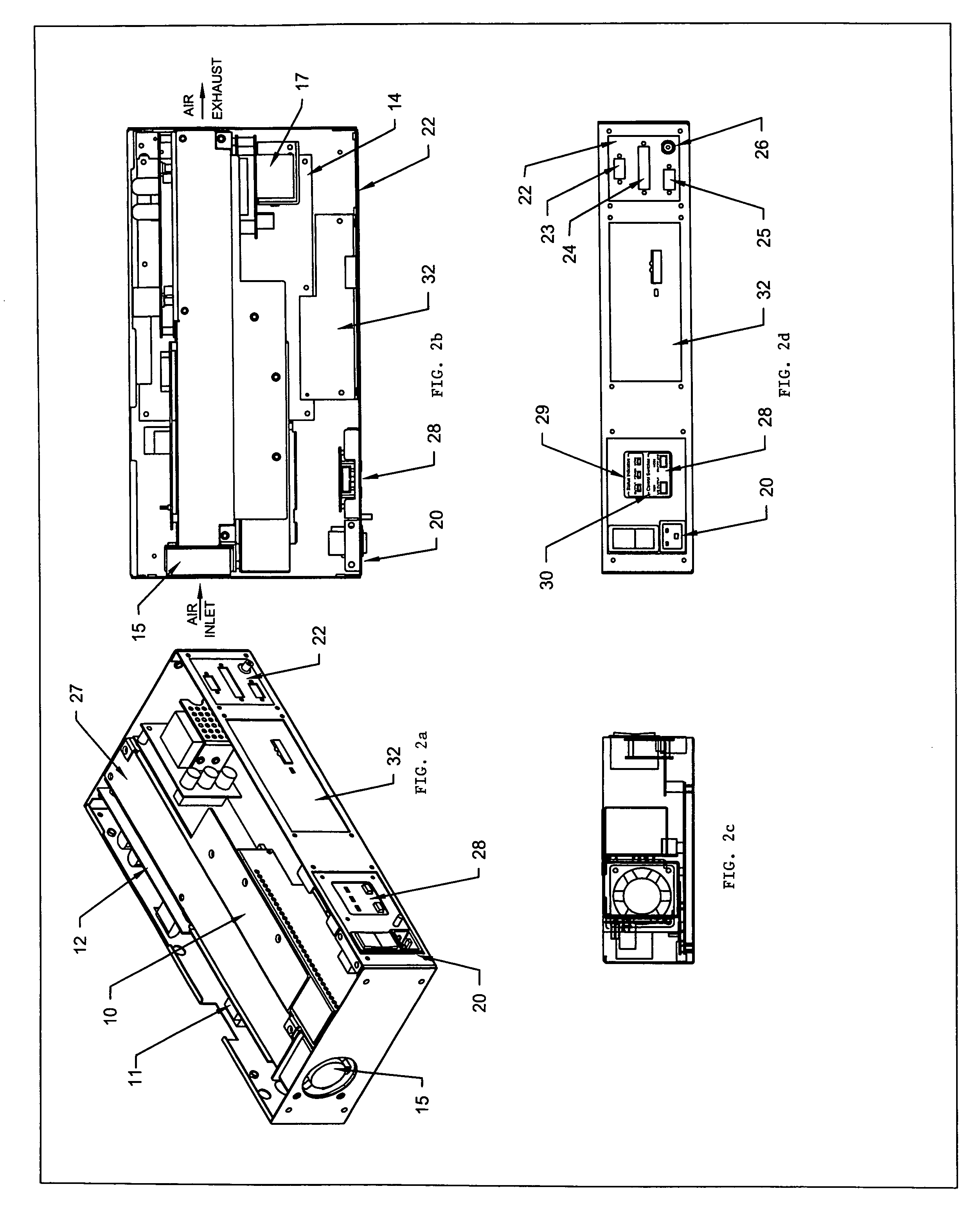
[0037]FIGS. 2a, 2b, 2c and 2d illustrate a base level ultrasonic power supply with the subasse...


PUM

PropertyMeasurementUnit
heightaaaaaaaaaa
heightaaaaaaaaaa
heightaaaaaaaaaa

Abstract

An ultrasonic generator comprising an input module for receiving a power signal. An output module for outputting an ultrasonic signal is also included in the generator. A motherboard is coupled to both the input module and the output module. The motherboard includes a digital controller adapted to control the input module and the output module.

Description

CROSS-REFERENCE TO RELATED APPLICATIONS[0001]This application claims priority to U.S. Provisional Application Ser. No. 60 / 754,681 filed Dec. 29, 2005.FIELD OF THE INVENTION[0002]This invention is directed generally to ultrasonic power supplies and is more particularly related to systems and methods for providing power to resonant ultrasonic stack assemblies used for ultrasonic welding or other applications that require ultrasonic energy.BACKGROUND OF THE INVENTION[0003]Ultrasonic welding is an efficient technique for joining component parts in manufacturing environments. Applications of ultrasonic welding include the welding of plastic parts and fabrics when manufacturing products such as automobile components, medical products, and other industrial or consumer products.[0004]In current ultrasonic welding devices, the ultrasonic generator includes many components for controlling and regulating the power delivered to an ultrasonic load. In many of these current ultrasonic generators,...

Claims


Application Information

Patent Timeline
Patent Type & Authority Patents(United States)
IPC IPC(8): B23K1/06B29C65/08
CPCB06B1/0261B29C66/924B29C66/962B29C65/08B29C66/90B29C66/949B29L2031/30B29L2031/753B29C66/9592B29C66/3022B29C66/8322B29C66/847B29C66/8748
Inventor JOHANSEN, DAVID K.LEONARD, CHARLES L.KLINSTEIN, LEOJURKOWSKI, WILLIAM E.RE, JOSEPH
Owner DUKANE IAS LLC
Why Eureka
Try Eureka