Image forming apparatus
- Summary
- Abstract
- Description
- Claims
- Application Information
AI Technical Summary
Benefits of technology
Problems solved by technology
Method used
Image
Examples
Embodiment Construction
[0019]Hereinafter, an embodiment of the present invention will be described with reference to the attached drawings. The embodiment which will be described hereinafter is an example embodying the present invention, and it has no characteristic of restricting a technical scope of the present invention.
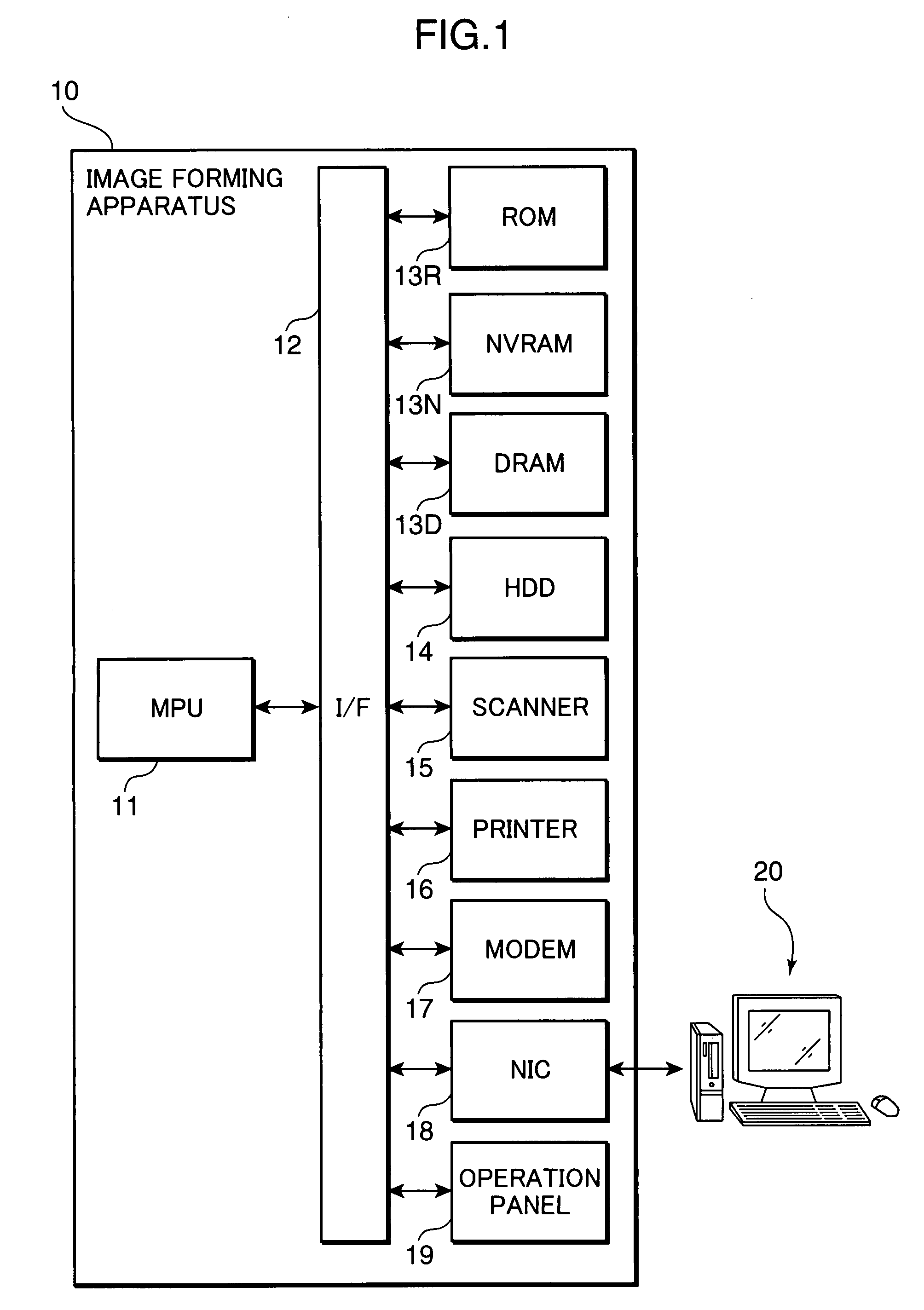
[0020]FIG. 1 is a block diagram schematically showing a hardware configuration of an image forming apparatus 10 according to an embodiment of the present invention.
[0021]The image forming apparatus 10 shown in FIG. 1 includes an MPU (Micro-Processing Unit) 11, an I / F (interface) 12, a ROM (Read Only Memory) 13R, a NVRAM (Non Volatile RAM) 13N, a DRAM (Dynamic RAM) 13D, an HDD (Hard Disk Drive) 14, a scanner 15, a printer 16, a modem 17, an NIC (Network Interface Card) 18 and an operation panel 19.
[0022]The MPU 11 controls the whole image forming apparatus 10 and is connected to the ROM 13R, the NVRAM 13N, the DRAM 13D, the HDD 14, the scanner 15, the printer 16, the modem 17, the NIC 18...
PUM
 Abstract
Description
Claims
Application Information
 - R&D
- Intellectual Property
- Life Sciences
- Materials
- Tech Scout
- Unparalleled Data Quality
- Higher Quality Content
- 60% Fewer Hallucinations
Browse by: Latest US Patents, China's latest patents, Technical Efficacy Thesaurus, Application Domain, Technology Topic, Popular Technical Reports.
© 2025 PatSnap. All rights reserved.Legal|Privacy policy|Modern Slavery Act Transparency Statement|Sitemap|About US| Contact US: help@patsnap.com


