Sliding pipe plug

a plug and sliding technology, applied in the field of plug systems, can solve the problems of leakage of electrical current, prone to wear and damage of pipes carrying water and other liquids, and easy intrusion of sewer pipes,

Active Publication Date: 2005-01-13
BUSAN TRANSPORTATION CORPORATION
View PDF11 Cites 27 Cited by
  • Summary
  • Abstract
  • Description
  • Claims
  • Application Information

AI Technical Summary

Benefits of technology

[0012] In accordance with the present application, a sliding pipe plug is presented which allows operations to be performed in a pipe without inserting more time consuming plugging mechanisms. Utilizing a sliding pipe plug according to the present invention, the pipe may be leak checked without completely filling a blocked off section. A sliding pipe plug according to the present invention allows a pipe to be filled to the level required for an operation such as FELL testing without completely plugging and filling a section of the pipe. In some embodiments, a sliding pipe plug according to the present invention can allow for operations to be performed in the pipe utilizing equipment for performing other operations. For example, FELL testing utilizing equipment normally utilized for high-pressure cleaning of the pipe can be performed with the sliding pipe plug.

Problems solved by technology

Pipes that carry water and other liquids are prone to wear and damage.
Sewer pipes, for example, may be prone to intrusion by tree roots or damage by ground movement.
Most sewer pipes consist of electrically insulating materials; however, a defect in the pipe that leaks sewage or other electrically conductive liquids will also leak electrical current.
Surcharging a pipe can cause backflow into residences and is considered an unwarranted risk by sewer maintenance supervisors.
A significant percentage of sewer pipe section cannot be FELL tested using this method to fill the pipe sections with water because they have a high gradient (i.e., deviation from the horizontal) and cannot be fully surcharged because the top of the downstream manhole may be lower than the crown of the pipe at the upstream manhole.
In addition, surcharging the pipe consumes a lot of time, in some instances more than half of the time required to carry out the test.

Method used


Image

  • Sliding pipe plug
  • Sliding pipe plug
  • Sliding pipe plug

Examples


Embodiment Construction

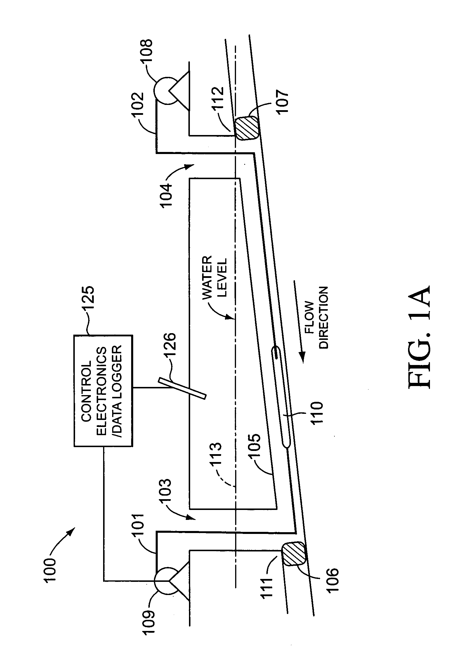
[0037]FIG. 1A illustrates a present system 100 for FELL testing of a pipe section 105. Section 105 is obstructed with pipe block 106 adjacent to access 103. The pipe block 106 is on the opposite side of joint 111 from the pipe section to be tested. Another pipe block 107 outside of joint 112 to access 104 may also be blocked. Haul line 102 is inserted into pipe section 105 via access 104. Haul line 102 hauls sonde 110 and cable 101 through pipe section 105 to access 104. Haul line 102 may be hauled using winch 108 in order to pull sonde 110 to the test start position adjacent to access 104. Pipe section 105 is filled with water to a level 113 which keeps pipe section 105 flooded. Sonde 110 is pulled back through the pipe section 105 by cable 101 on winch 109. Typically, sonde 110 is towed through pipe section 105 at a constant rate of about 30 ft / minute (10 m / minute), which optimizes the data acquisition process. Control electronics 125 controls winch 109 and voltage on sonde 110. C...


PUM


Abstract

A sliding pipe plug for working on and testing pipes is presented. The sliding pipe plug includes a center portion and a gasket disposed about the central portion. When towed through the pipe, the sliding pipe plug maintains a substantial seal against water flowing through the pipe. In some embodiments, a flexible gasket can be utilized to allow for substantial sealing while the sliding pipe plug is traversing obstacles in the pipe. The sliding pipe plug according to the present invention can be utilized in pipes where conventional plugs are inconvenient. For example, in FELL testing a sewage line, a sliding pipe plug can be attached to a sonde cable and the testing can proceed without plugging and surcharging all of the section of pipe to be tested. In some embodiments, the sliding pipe plug includes a break-away section that allows the seal against water flowing through the pipe to be broken when the sliding pipe plug is pulled in a direction opposite the towing direction. In some embodiments, the sliding pipe plug includes a centering section that keeps the sliding pipe plug essentially in the center of the pipe.

Description

RELATED APPLICATIONS [0001] The present application is related to U.S. patent application Ser. No. 10 / 306,403, “Sliding Pipe Plug”, to R. J. Harris, assigned to the same assignee as is the present disclosure, herein incorporated by reference in its entirety.BACKGROUND [0002] 1. Field of the Invention [0003] The present invention relates to testing of pipes and, in particular, to a plug system for restricting the water flow through a pipe. [0004] 2. Description of Related Art [0005] Pipes that carry water and other liquids are prone to wear and damage. Sewer pipes, for example, may be prone to intrusion by tree roots or damage by ground movement. Testing can be routinely performed on the pipes in order to ascertain if the pipe is damaged and leaking. Additionally, testing may be performed on pipes to locate leaks in order to facilitate repairs. [0006] One method for testing pipes is with the use of a Focused Electrode Leak Locater (FELL) system. The FELL system locates defects by che...

Claims


Application Information

Patent Timeline
Patent Type & Authority Applications(United States)
IPC IPC(8): G01M3/00G01M3/18
CPCG01M3/18G01M3/005
Inventor HARRIS, R. J.
Owner BUSAN TRANSPORTATION CORPORATION
Why Eureka
Try Eureka