Vehicle occupant sensing system having an upper slide member with an emitter interference member

a technology of emitter interference and vehicle occupants, which is applied in the direction of pedestrian/occupant safety arrangements, instruments, chairs, etc., can solve the problems of increased deployment force and speed required to restrain a one hundred eighty-pound male, high cost of supplemental inflatable restraints and their associated deployment systems, and increased deployment costs. , to achieve the effect of extending the operational life of vehicle occupant sensing systems, reducing the number of occupants, and ensuring safety

Inactive Publication Date: 2007-08-21
LEAR CORP
View PDF114 Cites 6 Cited by
  • Summary
  • Abstract
  • Description
  • Claims
  • Application Information

AI Technical Summary

Benefits of technology

[0018]One advantage of the present invention is that the vehicle occupant sensing system includes an upper slide member with at least one interference member. The interference member provides more robust attachment of the emitter to the upper slide member. Also, the interference member provides visual confirmation that the emitter is positioned properly within the retainer. As such, the emitter is less likely to become detached from the upper slide member, thereby extending the operational life of the vehicle occupant sensing system. Another advantage of the present invention is that the interference member allows the upper slide member to be assembled and the emitter to be magnetized and tested before the upper slide member is attached to other components of the sensor assembly. This can allow for more efficient assembly of the sensor assembly.

Problems solved by technology

These supplemental inflatable restraints and their associated deployment systems are expensive and over time this deployment strategy was deemed not to be cost effective.
However, the airbag deployment force and speed required to restrain a one hundred eighty pound male exceeds that which are required to restrain smaller occupants, such as some females and small children.
However, the airbag deployment force and speed may inappropriately restrain a person sitting otherwise.
While the Saunders et al. occupant seat sensing system teaches a sensor / emitter pair that may sense the presence of a vehicle seat occupant, it suffers from certain disadvantages associated with the fact that it is mounted within the seat cushion of the vehicle seat.
This is especially true over time as the seat cushion becomes worn.
Thus, the housing can be deformed in an irregular manner resulting in false readings generated by the sensor / emitter pair.
Over time, loading of the system may cause the emitter to detach from the surrounding emitter portion.

Method used


Image

  • Vehicle occupant sensing system having an upper slide member with an emitter interference member
  • Vehicle occupant sensing system having an upper slide member with an emitter interference member
  • Vehicle occupant sensing system having an upper slide member with an emitter interference member

Examples


second embodiment

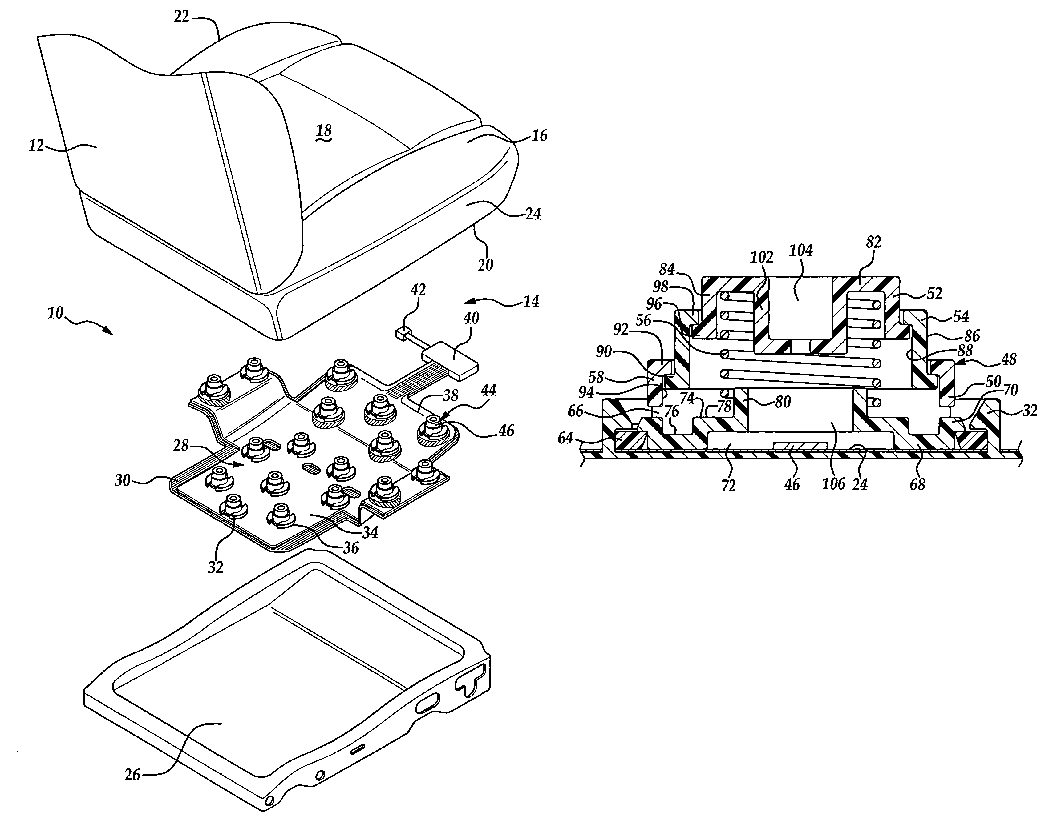
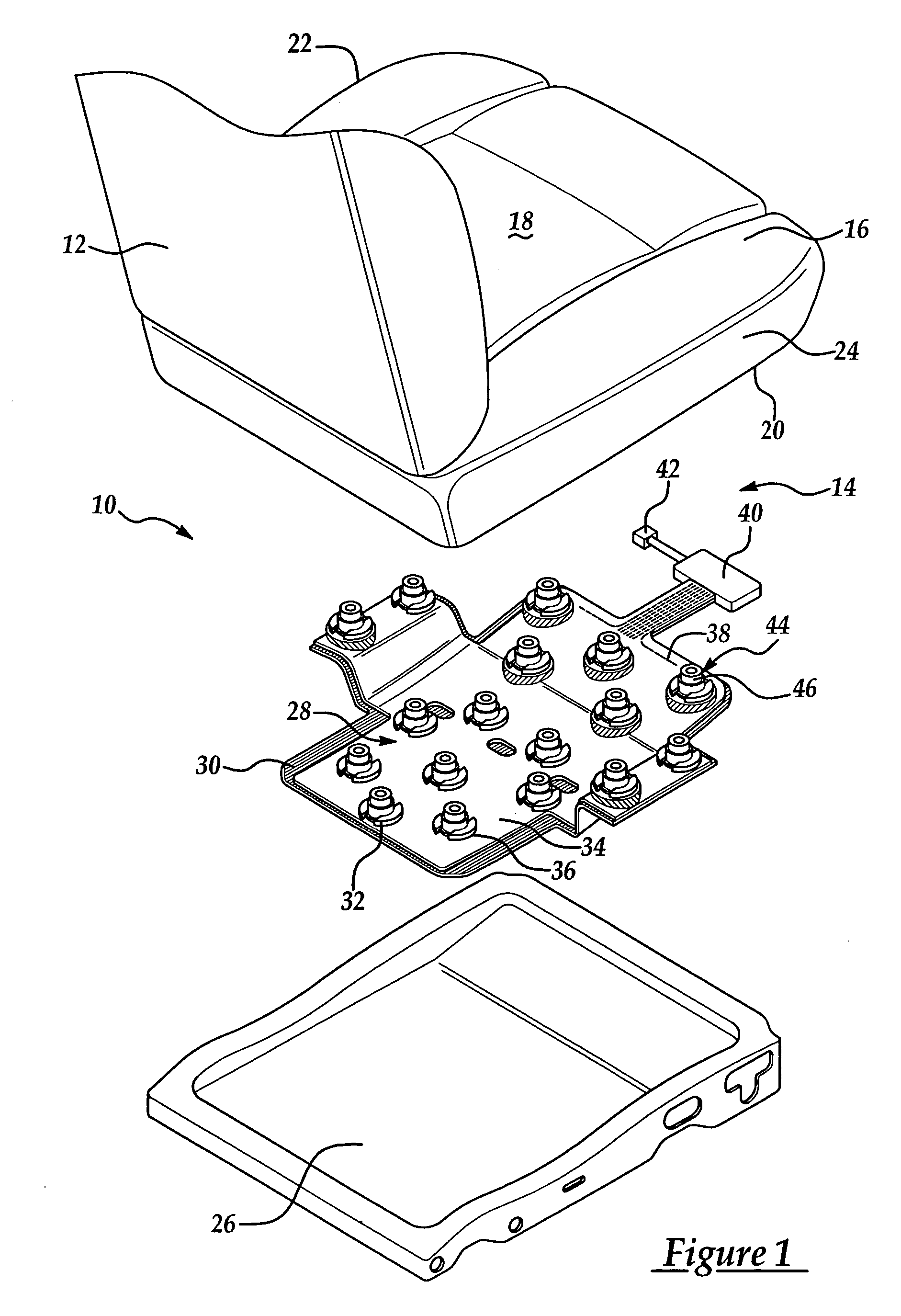
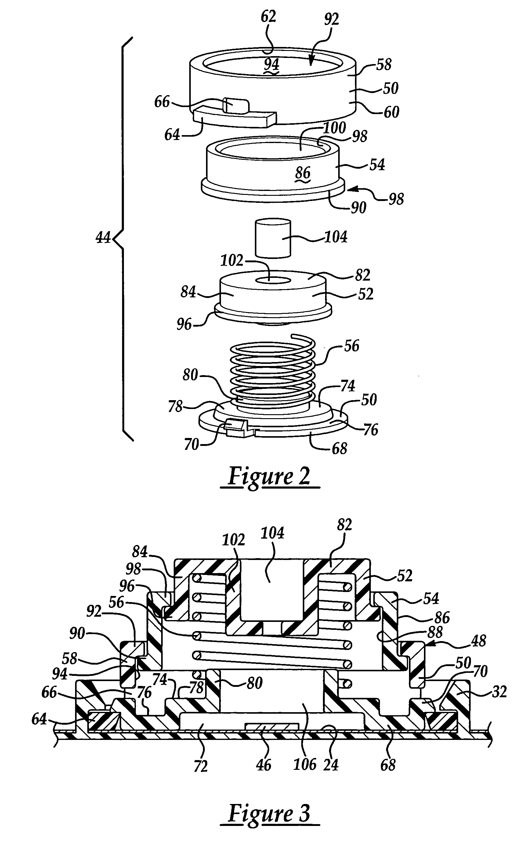
[0058]Turning now to FIGS. 5 through 7, a low profile sensor assembly is generally indicated at 244 where like numerals increased by 200 are used to designate like structure with respect to the embodiment illustrated in FIGS. 2 through 4. The sensor assembly 244 can be included in the vehicle seat assembly 10 of FIG. 1.

[0059]As shown, the low profile sensor assembly 244 comprises a housing 248. The housing 248 includes a base 250 having an attached base guide 258 and a retainer 268. The low profile sensor assembly 244 also includes an upper slide member 252 supported for movement toward and away from the base 250. Specifically, the upper slide member 252 is sized to slidably move in an axial direction through a bore 262 of the base 250. The sensor assembly 244 also includes a biasing member 256 extending between the base 250 and the upper slide member 252. As in the preferred embodiment illustrated in FIG. 1-4, the biasing member 256 employed in the embodiment illustrated in FIG. 5-...

third embodiment

[0067]Turning now to FIG. 8, a sensor assembly is generally indicated at 444 where like numerals increased by 400 are used to designate like structure with respect to the embodiment illustrated in FIGS. 2 through 4. The sensor assembly 444 may be employed with the vehicle occupant sensing system 28 to detect a condition of the vehicle seat assembly 10 of FIG. 1.

[0068]As shown, the sensor assembly 444 includes a base 450, which is similar to the base 50 described above in relation to FIGS. 2-4. The base 450 includes a base guide 458, which defines a bore 462 extending axially therethrough. The base 450 also includes an upper flange 498 extending radially outward from the upper end of the base guide 458. Furthermore, the sensor assembly 444 includes an upper slide member 452, which is moveably attached to the base 450. The upper slide member 452 includes a circular upper disc portion 482 and a support wall 484 extending downward from the periphery of the upper disc portion 482. The di...


PUM


Abstract

A vehicle occupant sensing system adapted for detecting a condition of a vehicle seat assembly including at least one emitter and at least one sensor disposed spaced relative to the emitter. The sensor is operable to detect relative distance between the emitter and the sensor to thereby detect the condition of the vehicle seat assembly. The vehicle occupant sensing system also includes at least one sensor assembly having a base and an upper slide member moveable toward and away from the base. The upper slide member includes at least one interference member that generates an interference fit between the emitter and the interference member to thereby securely mount the emitter to the upper slide member. The vehicle occupant sensing system may be employed in a vehicle seat to detect a condition of the vehicle seat.

Description

CROSS-REFERENCE TO RELATED APPLICATIONS[0001]This application is a continuation-in-part of U.S. Ser. No. 10 / 748,536, entitled “Vehicle Occupant Sensing System Having a Low Profile Sensor Assembly” and filed Dec. 30, 2003, now U.S. Pat. No. 7,021,707, which is a continuation-in-part of U.S. Ser. No. 10 / 606,649, entitled “Encapsulated Spring Sensor Assembly” and filed Jun. 26, 2003.BACKGROUND OF THE INVENTION[0002]1. Field of the Invention[0003]The present invention relates, generally, to vehicle occupant sensing systems and, more particularly, to a vehicle occupant sensing system having an upper slide member with an emitter interference member.[0004]2. Description of the Related Art[0005]Automotive vehicles employ seating systems that accommodate the passengers of the vehicle. The seating systems include restraint systems that are calculated to restrain and protect the occupants in the event of a collision. The primary restraint system commonly employed in most vehicles today is the ...

Claims


Application Information

Patent Timeline
Patent Type & Authority Patents(United States)
IPC IPC(8): A47C31/12A47C7/62B60N2/00B60R21/01B60R21/015G01G19/414
CPCB60N2/002B60R21/01516G01G19/4142
Inventor YOUNG, OLIVER J.NATHAN, JOHN F.RICARD, CHRISTOPHER T.
Owner LEAR CORP
Why Eureka
Try Eureka