Low profile push on metal doghouse

a metal doghouse and low-profile technology, applied in the direction of snap fasteners, buckles, transportation and packaging, etc., can solve the problems of requiring some of the fastener designs to be very small, the area between the components, and the b-pillar and the appliqué is often very limited, so as to minimize the potential for a read condition and simplify the mold design

Active Publication Date: 2017-05-23
MAGNA INTERNATIONAL INC +1
View PDF4 Cites 3 Cited by
  • Summary
  • Abstract
  • Description
  • Claims
  • Application Information

AI Technical Summary

Benefits of technology

[0009]The present invention simplifies mold design, minimizes potential for a read condition, and provides a robust engagement for a winged clip type fastener in limited space.
[0010]It is an object of the invention to provide for attachment of the exterior ornamentation of an appliqué in a limited packaging space that is robust without introducing a read condition or breakage. It is another object of the invention to provide an attachment which is toolable in an injection molded part and which will meet a minimum pull off force without breakage while applied to the vehicle.

Problems solved by technology

The packaging space in vehicles is often very limited due to the number of components used to assemble the vehicle, the size of the vehicle, and the like.
Some of the area between components, such as a B-pillar and an appliqué, is very limited.
This requires some of the fastener designs to be very small.
Molded-in features, such as a doghouse, often cause a “read” condition on the show surface of a part resulting from differences in cooling temperatures, caused by differences in mass / volume of the resin between the feature and the substrate.
The limited space also causes a tooling condition that is very fragile due to the reduced size.
A feature of the type described above has a minimum workable size which does not facilitate the doghouse having suitable strength.
The size of the part and the proximity of adjacent features limit the packaging space and travel of movable feature (lifters) in the mold.
These designs also lack suitable strength and do no meet space limitations in current low profile designs.
This presents further space constraints which are unaddressed by current designs.

Method used


Image

  • Low profile push on metal doghouse
  • Low profile push on metal doghouse
  • Low profile push on metal doghouse

Examples


Embodiment Construction

[0019]The following description of the preferred embodiment(s) is merely exemplary in nature and is in no way intended to limit the invention, its application, or uses.

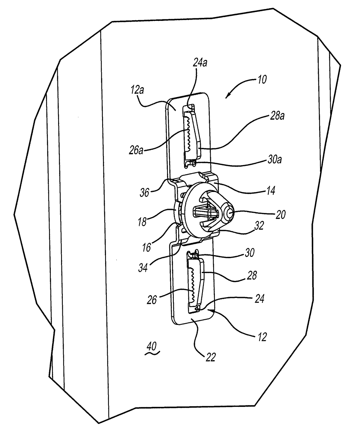
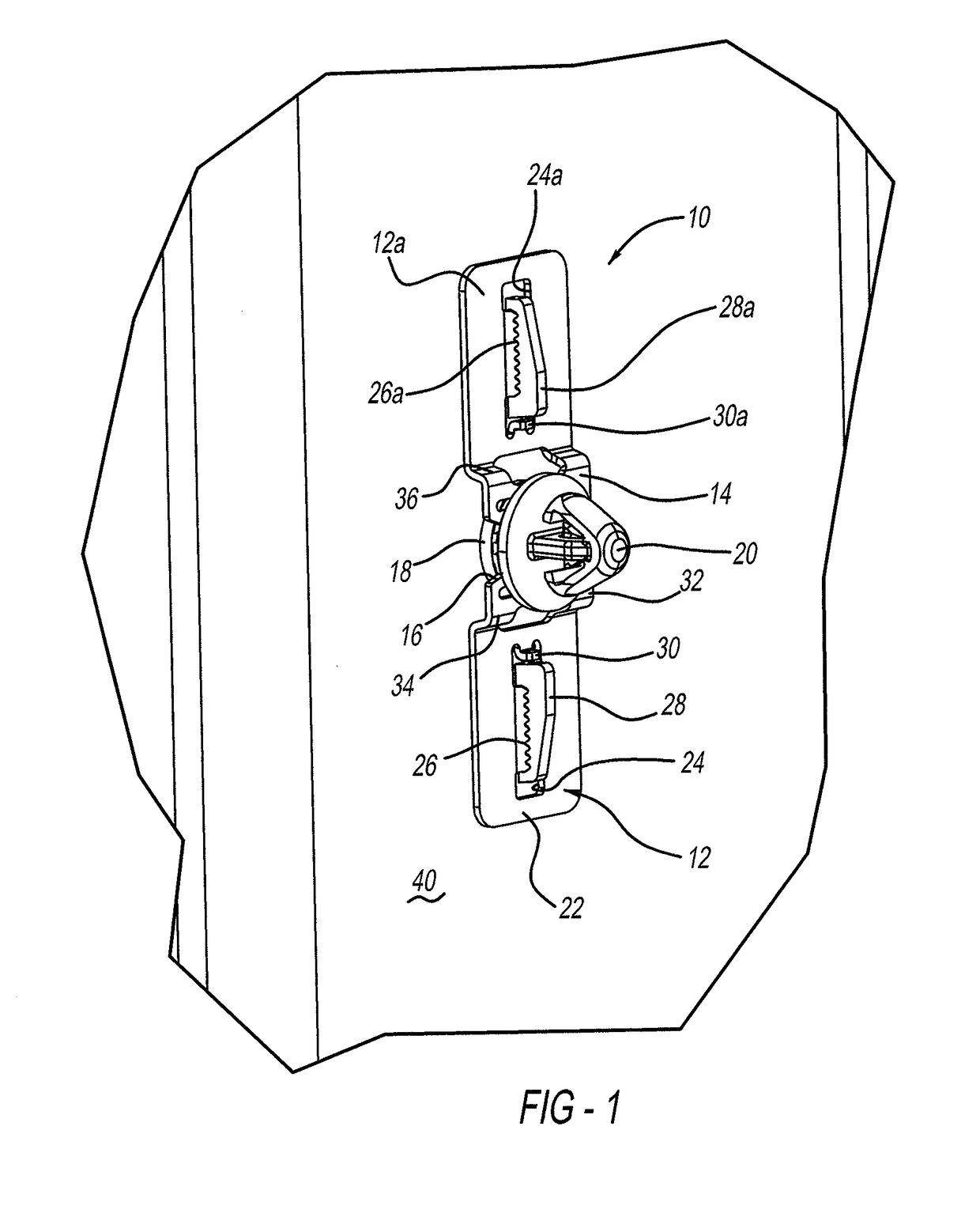
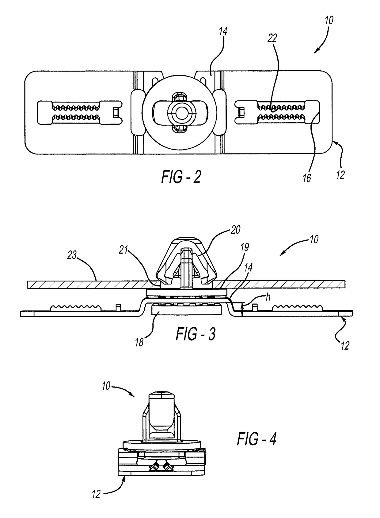
[0020]Referring now to FIGS. 1-6 there is provided a push on doghouse generally shown at 10 which is made from a metal material, preferably spring steel. Spring steel is defined as a steel that is processed in a manner to give it elastic properties and returns it to its original shape after removal of a load force. The composition of spring steel is generally defined to be low alloy, medium carbon (e.g. 0.30%-0.59% carbon content by weight of the steel) or high carbon content (e.g., 0.60%-0.99% carbon content by weight of the steel). Spring steel used in accordance with the present invention also has a high yield strength of generally 150-1650 MPa, ideally 250-690 MPa or preferably 250-520 MPa.

[0021]The doghouse 10 includes a formed low profile spring steel base generally indicated at 12. The base 12 includes a slight...


PUM

PropertyMeasurementUnit
yield strengthaaaaaaaaaa

Abstract

A push on doghouse retainer arrangement used for providing a connection between the B-pillar of an automobile, and an appliqué having a high-gloss surface, or “show surface.” The a push on doghouse includes a formed low profile spring steel base and a slightly raised low profile doghouse portion, which includes a slot for receiving a base of a clip portion. The base also includes at least one attachment aperture. The attachment aperture includes an effective amount of serrations for holding of the doghouse onto a low profile rib molded into the part. The present invention simplifies mold design, minimizes potential for a read condition, and provides a robust engagement for a winged clip type fastener in limited space.

Description

CROSS-REFERENCE TO RELATED APPLICATIONS[0001]This application claims the benefit of U.S. Provisional Application No. 61 / 617,457, filed Mar. 29, 2012.FIELD OF THE INVENTION[0002]The present invention relates to a method for providing a secure connection between a first attachable part such as an appliqué and the pillar or other component part of an automobile.BACKGROUND OF THE INVENTION[0003]The components of an automobile are connected together in many different ways. One type of connection uses a fastener, such as a bolt or screw.[0004]The packaging space in vehicles is often very limited due to the number of components used to assemble the vehicle, the size of the vehicle, and the like. Some of the area between components, such as a B-pillar and an appliqué, is very limited. This requires some of the fastener designs to be very small. Typically, one type of connector used for retaining two components is a molded “doghouse.” A doghouse is a molded-in feature used to attach a second...

Claims


Application Information

Patent Timeline
Patent Type & Authority Patents(United States)
IPC IPC(8): F16B5/06F16B21/09B60R13/02F16B21/20
CPCB60R13/0206F16B5/0657F16B21/09B60R13/025F16B5/065F16B21/20Y10T24/304Y10T29/49947
Inventor BACHELDER, THEODORE J.LYON, ADAM M.ANDOR, RONALD J.GIGNILLIAT, MICHAEL S.PATTERSON, MATTHEW C.ROLL, JAMES R.
Owner MAGNA INTERNATIONAL INC
Why Eureka
Try Eureka