
Vertical axis wind engine

a technology of wind turbines and vertical axes, which is applied in the direction of rotors, marine propulsion, vessel construction, etc., can solve the problems of limiting the rotation angle, and achieve the effect of reducing the size of each airfoil, facilitating manufacturing, and reducing the force of wind on each airfoil

Inactive Publication Date: 2007-08-21
SHIH CHI KUANG
View PDF6 Cites 45 Cited by
  • Summary
  • Abstract
  • Description
  • Claims
  • Application Information

AI Technical Summary

Benefits of technology

The design enhances wind energy conversion efficiency, reduces component damage from strong winds, and improves operational stability and manufacturing simplicity by allowing airfoils to adapt to varying wind conditions while maintaining structural integrity.

Problems solved by technology

Thus, the pivot limitation of each airfoil is lifted for causing the airfoil to pivot so as to have a contour to offer the least resistance to wind.

Method used


Image

  • Vertical axis wind engine
  • Vertical axis wind engine
  • Vertical axis wind engine

Examples


Embodiment Construction

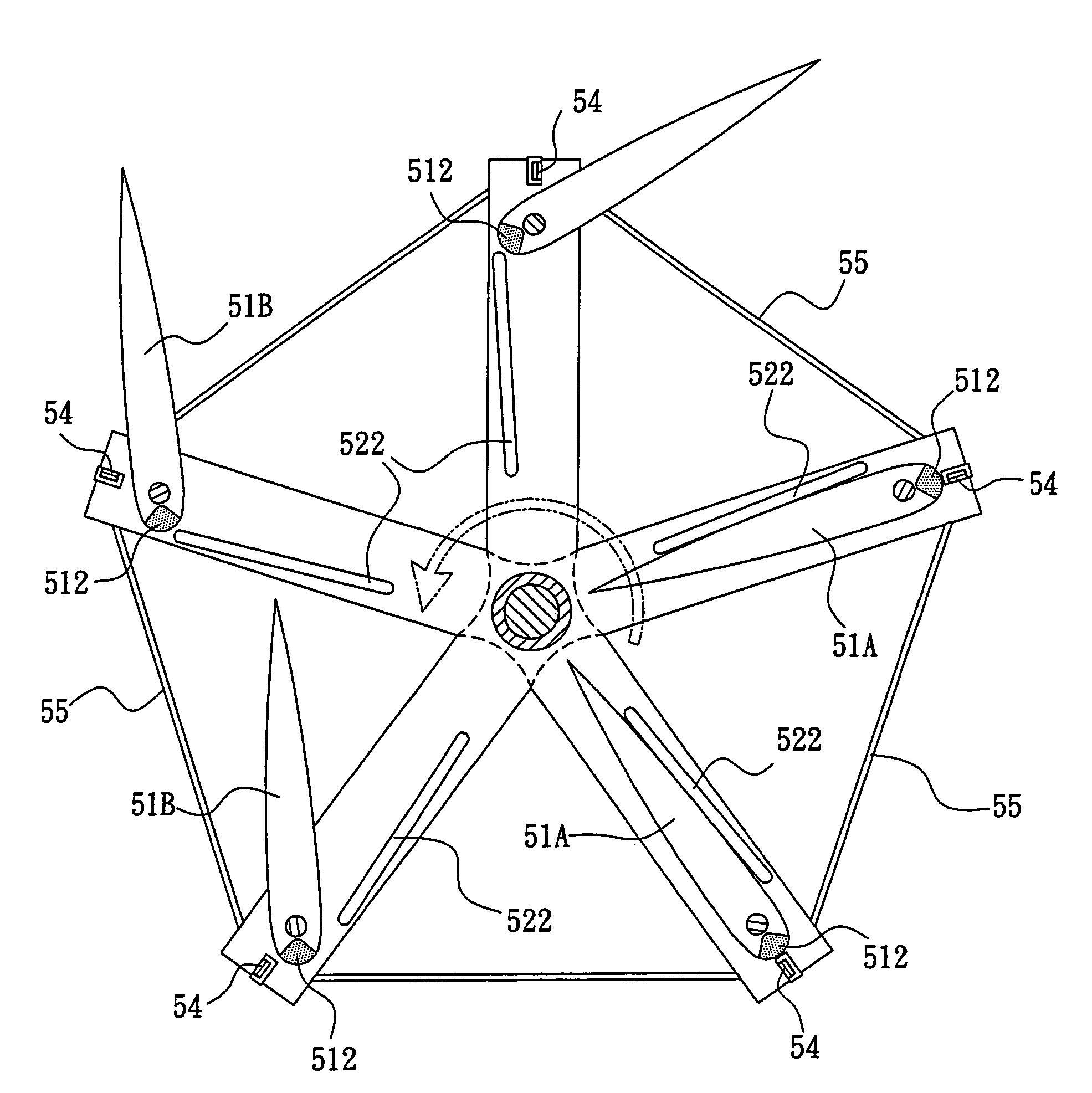
[0026]Referring to FIG. 5, there is shown a vertical axis wind engine 50 of a first preferred embodiment of the invention. The wind engine 50 comprises a central, vertical axis 53 mounted on a base on the ground, a transmission 60 provided in a lower portion of the vertical axis 53, and a drive shaft (not shown) in the transmission 60 for coupling rotational movement from the vertical axis 53 to an electric power generator (not shown). A frame comprises a plurality of arms 52 and another component as detailed later. The frame is rotatable about the vertical axis 53 (i.e., having its center rotatably coupled to the vertical axis 53). Rotation of the frame causes the vertical axis 53 to rotate the same. The frame comprises a plurality of (five are shown) upper arms 52, a plurality of (five are shown) lower arms 52, and a sleeve put on the vertical axis 53 for connecting the upper arms 52 to the lower arms 52 such that each pair of arms 52 (i.e., an upper arm 52 and a corresponding low...


PUM


Abstract

The present invention is to provide a vertical axis wind engine comprising at least one arm each having its center rotatably coupled to a vertical axis mounted on a base on the ground, each pair of the upper and lower arms adapted to define an airfoil receiving space for pivotably mounting an airfoil by pivot pins thereof; and at least one elastic stop member each provided on the arm proximate the airfoil and spaced from the pivot pins, each stop member adapted to limit a pivot angle of the airfoil and lift the pivot limitation for allowing the airfoil to pivot when the airfoil experiences a wind force larger than a maximum resistance force thereof, preventing the components of the wind engine from being damaged by strong wind or when the wind engine is operating in high speed.

Description

FIELD OF THE INVENTION[0001]The present invention relates to vertical axis wind engines, and more particularly to such a vertical axis wind engine capable of preventing the arms, the airfoils, and other components of the wind engine from being damaged by strong wind or when the wind engine is operating in high speed.BACKGROUND OF THE INVENTION[0002]Conventionally, a wind engine is classified as a horizontal axis wind engine or a vertical axis wind engine based on the orientation of rotating axes of its vanes. For vanes of the vertical axis wind engine, they are pivotably mounted in a frame. The frame is fixedly coupled to a vertical axis. Its transmission is provided near the ground. To the contrary, in the horizontal axis wind engine each vane has its horizontal axis provided above the ground by a relatively long distance. Moreover, each of a plurality of vanes of a vertical axis wind engine can adapt itself to wind by providing a wide contour in a windward condition for fully taki...

Claims


Application Information

Patent Timeline
Patent Type & Authority Patents(United States)
IPC IPC(8): F03D3/06
CPCB63H7/00B63H9/00
Inventor SHIH, CHI-KUANG
Owner SHIH CHI KUANG
Learn More