Suppressor for firearms

a suppressor and firearm technology, applied in the direction of weapons, weapon components, etc., can solve the problems of affecting the operation of the receiver, contaminating the barrel with solids, and high stress, and achieve the effect of reducing or eliminating the backpressure of prior suppressors, low stress, and low cos

Active Publication Date: 2020-01-14
THOMAS GERALD R
View PDF48 Cites 11 Cited by
  • Summary
  • Abstract
  • Description
  • Claims
  • Application Information

AI Technical Summary

Benefits of technology

[0003]The present invention is a suppressor that reduces or eliminates the backpressure of prior suppressors while providing high effectiveness according to acoustics testing by the inventor. The gas flow path through the suppressor is much less flow-restrictive than the flow path through the bullet passage, making the suppressor the path of least resistance. Most of the length of the suppressor is backward from the muzzle, minimizing forward extension. Sound is reflected internally. Aperture placement maximizes sound reduction with minimal gas flow restriction. This suppressor design allows gases to flow unimpeded through the suppressor.

Problems solved by technology

This contaminates the barrel with solids, and can affect operation of the receiver due to contamination and departure from the design backpressure.
This causes timing issues with the gas system that result in high stresses, accelerated wear, damaged extractors and cases, etc.
Shorter barrels may be more affected.
For example a suppressor that works on a 20-inch barrel may impair the repeating mechanism of a rifle with 14.5-inch barrel.
Current suppressors cause high backpressure because they try to contain the blast, preventing it from flowing through the suppressor.
Another disadvantage of prior suppressors is that they make the gun longer by extending forward of the barrel.

Method used


Image

  • Suppressor for firearms
  • Suppressor for firearms
  • Suppressor for firearms

Examples


Embodiment Construction

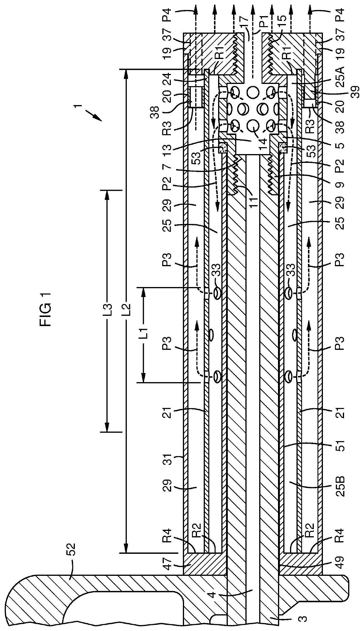
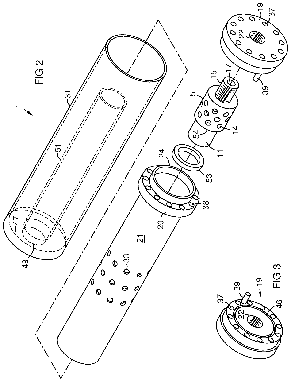
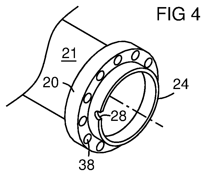
[0016]FIG. 1 is a sectional view of a suppressor 1 mounted on a barrel 3 of a firearm. A conduit 5 of the suppressor extends forward from the muzzle 7. The back end 9 of the conduit has internal threads 11 engaging external threads on the muzzle. The conduit has a bullet passage 13 for bullets to pass from the barrel bore 4 through the conduit, preferably without contact. The front end or exit 17 of the bullet passage closely fits the diameter of the bullet without contact. This minimizes propellant gas venting to the atmosphere via the bullet exit instead of going through the suppressor. An inner shell 21 has a front end 24 sealed around the front end of the conduit, for example by abutting a front plate 19 attached to the conduit by threads 15 or other means. The inner shell has a back end that extends backward over the barrel, forming a continuous inner annular chamber 25 with a first portion 25A around the conduit and a second portion 25B longer than the first portion around a f...


PUM


Abstract

A conduit (5) with a bullet passage (13, 17) extends forward from a gun muzzle (7). Inner and outer concentric chambers (25, 29) surround the conduit and a forward portion of the barrel (3). A gas path (P2, P3, P4) is provided through sides of the conduit into the inner chamber, thence to the outer chamber, and then exits to the atmosphere at the front of the outer chamber. Each chamber has longitudinal lines of sight between front and back sound reflectors (R1-R2, R3-R4), and no longitudinal line of sight from the back reflector (R2, R4) to the atmosphere. The gas path through the suppressor is at least 6 times less flow-restrictive than the gas path through the bullet exit (17) or back into the barrel bore (4), minimizing backpressure. The gas path (P3) between the inner and outer chambers is through apertures (33) limited to a lengthwise middle portion of an inner shell (21) that divides the chambers (25, 29).

Description

FIELD OF THE INVENTION[0001]This invention relates to suppressors for firearms, and particularly to sound suppressors that minimize back pressure and minimize extension of the suppressor forward of the muzzle.BACKGROUND OF THE INVENTION[0002]Sound suppressors on firearms create backpressure that causes some of the propellant gas in the suppressor to flow back into the barrel and gas system after the bullet exits. This contaminates the barrel with solids, and can affect operation of the receiver due to contamination and departure from the design backpressure. Current suppressors maintain high pressures in the bore and gas systems longer than the system was designed to handle. This causes timing issues with the gas system that result in high stresses, accelerated wear, damaged extractors and cases, etc. An entire cottage industry has grown to provide adjustable gas blocks to address these shortcomings. Shorter barrels may be more affected. For example a suppressor that works on a 20-i...

Claims


Application Information

Patent Timeline
Patent Type & Authority Patents(United States)
IPC IPC(8): F41A21/30
CPCF41A21/30
Inventor THOMAS, GERALD R.
Owner THOMAS GERALD R
Why Eureka
Try Eureka