Sheet feeding device with variable faced roller and integrated sheet guides

a feeding device and variable face technology, applied in the direction of transportation and packaging, thin material processing, article separation, etc., can solve the problems of difficult to reduce the size of the sheet feeding device, the feeding device may not be able to feed the sheet of paper, and the installation posture is limited, so as to achieve simple and compact structure

Inactive Publication Date: 2008-08-05
SEIKO EPSON CORP
View PDF30 Cites 4 Cited by
  • Summary
  • Abstract
  • Description
  • Claims
  • Application Information

AI Technical Summary

Benefits of technology

[0011]It is therefore an object of the invention to provide a sheet feeding device having a simple and compact structure with its installment posture being least limited and capable of feeding plural sheets of paper in a reliable manner even when the paper leading ends are aligned somewhat irregularly.

Problems solved by technology

However, when the sheet feeding roller is disposed at the downstream side of the sheet feeding device in the sheet feeding direction, in a case where the leading ends of sheets of paper are not aligned neatly, there may be a sheet of paper whose leading end does not reach the position at which the leading end is supposed to come into contact with the sheet feeding roller.
In such a case, the sheet feeding roller fails to pull in the leading end of the sheet of paper, and the sheet feeding device may become unable to feed the sheet of paper.
A sheet feeding cassette is necessary, however, with the method for positioning sheets of paper on the left, right, top, and bottom precisely by placing the sheets of paper horizontally, and this method makes it difficult to reduce the sheet feeding device in size.
The installation posture is limited, however, because sheets of paper cannot be fed unless they are set in the vertical direction.

Method used


Image

  • Sheet feeding device with variable faced roller and integrated sheet guides
  • Sheet feeding device with variable faced roller and integrated sheet guides
  • Sheet feeding device with variable faced roller and integrated sheet guides

Examples


Embodiment Construction

[0078]Embodiments of the invention will be described below in detail with reference to the accompanying drawings.

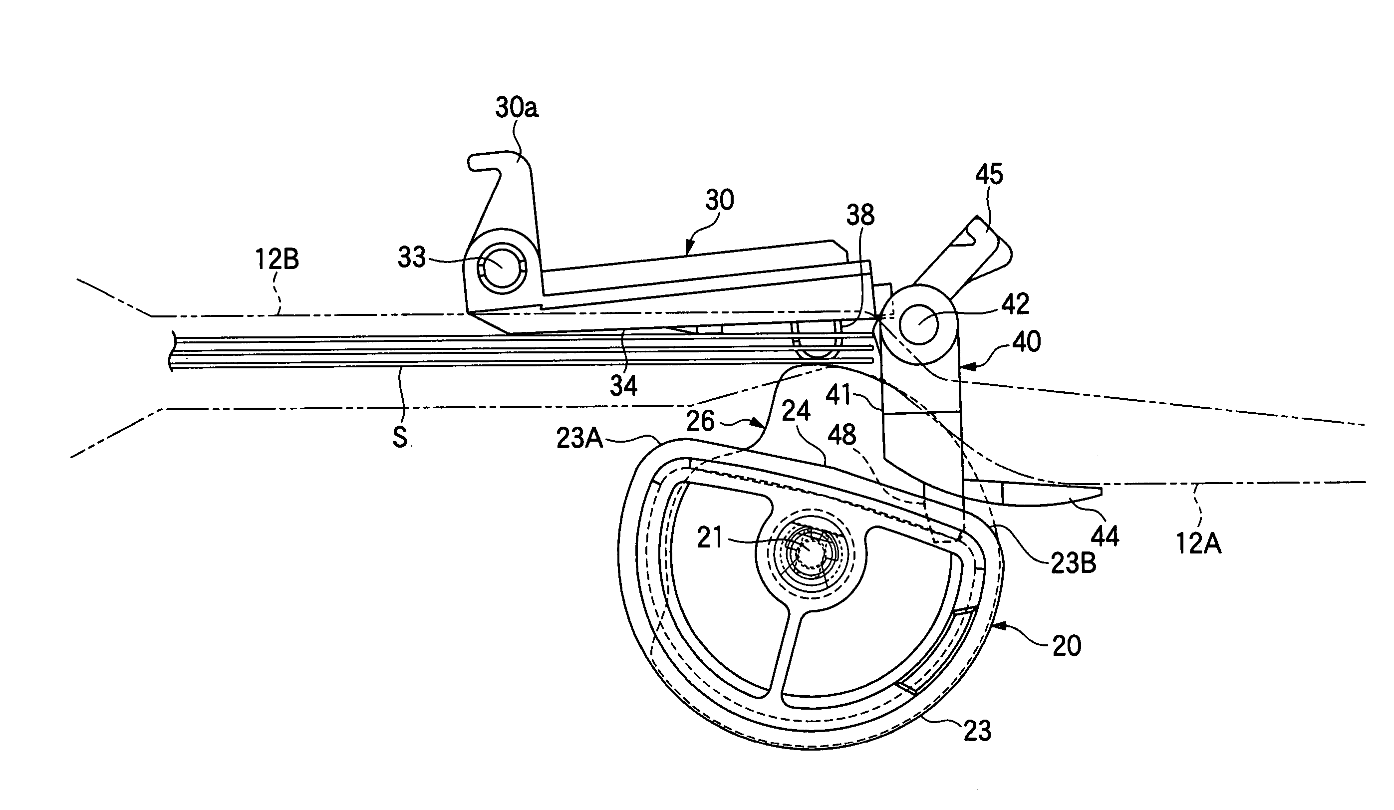
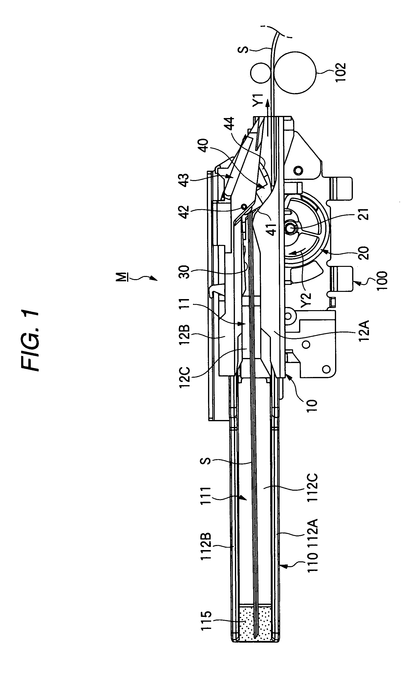
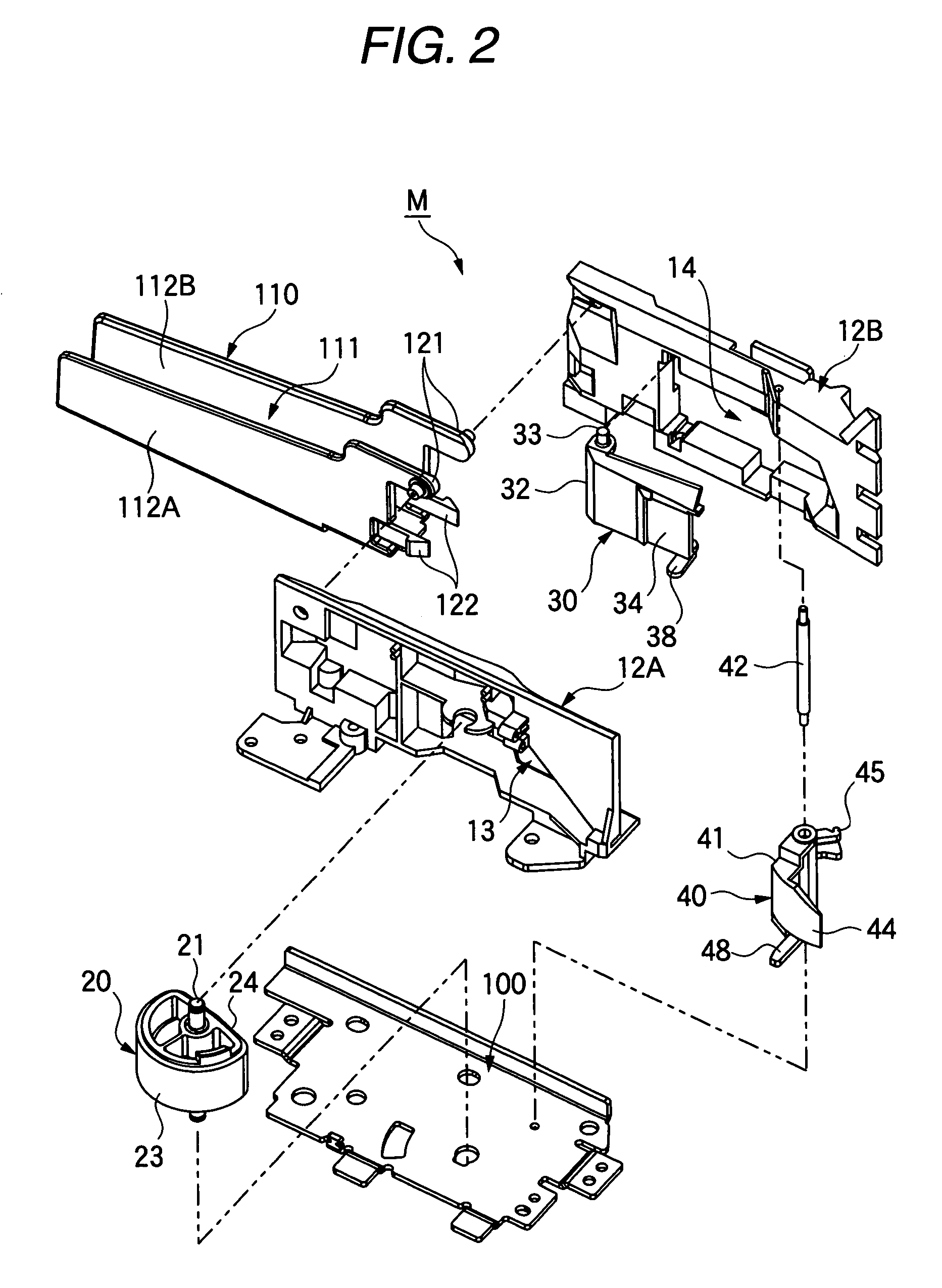
[0079]As is shown in FIG. 1, a sheet feeding device M according to one embodiment of the invention is configured in such a manner that checks (sheets of paper) S are set in a sheet holder 10 in a standing posture with their leading ends (the right ends in the drawing) being oriented in the horizontal direction (in a direction indicated by an arrow Y1), and respective checks S are fed in the same posture in the horizontal direction (in the direction indicated by the arrow Y1). The sheet holder 10 attached to a frame 100 comprises a pair of side walls 12A and 12B defining a sheet inserting section 11 in which a pile of plural checks S can be manually inserted, and a bottom wall 12C on which the lower ends of checks S are mounted (see FIG. 2).

[0080]Further, a sub sheet holder 110 is detachably linked to the end portion of the sheet holder 10 of this embodiment. The sub sheet...


PUM


Abstract

A sheet feeding roller has an outer circumferential face which includes a generally flat portion and a curved portion. A first pivotable member is movable between a first position and a second position in accordance with the rotation of the sheet feeding roller. The first pivotable member has a first contact face and an extended member extended from a free end portion of the first pivotable member toward a downstream side of a sheet feeding direction. The first pivotable member is moved to the second position when a sheet medium is placed between the sheet feeding roller and the first pivotable member. The first pivotable member is returned to the first position when a trailing end of the sheet medium faces the flat portion of the sheet feeding roller while the extended member of the first pivotable member comes in contact with the sheet medium.

Description

BACKGROUND OF THE INVENTION[0001]The present invention relates to a sheet feeding device used in a data reading apparatus, a printing apparatus or the like to feed plural sheets of paper one by one to a processing section.[0002]A roller type sheet feeding device used in a printer, a facsimile machine, a copying machine or the like has been generally known as a sheet feeding device.[0003]In most cases, the roller type sheet feeding device of this kind has a cylindrical sheet feeding roller disposed at the downstream side in a sheet feeding direction, so that a sheet of paper is fed as the sheet feeding roller pulls in the sheet of paper from the vicinity of the leading end thereof.[0004]This is because sheet feeding operations become more stable regardless of the paper rigidity by feeding sheets of paper while holding the vicinity of their leading ends. In addition, for a sheet feeding device of a type in which a separating pad is disposed downstream of a sheet feeding roller to sepa...

Claims


Application Information

Patent Timeline
Patent Type & Authority Patents(United States)
IPC IPC(8): B65H3/52B65H3/06
CPCB65H3/0638B65H3/5238B65H2404/1112
Inventor OGAYA, SHUNPEIHIRABAYASHI, KENICHI
Owner SEIKO EPSON CORP
Why Eureka
Try Eureka