Electrical box for single fastener attachment

Inactive Publication Date: 2007-08-21
HERTH GREG
View PDF3 Cites 10 Cited by
  • Summary
  • Abstract
  • Description
  • Claims
  • Application Information

AI Technical Summary

Benefits of technology

[0007]It is also an object of the present invention to provide an electrical box equipped with anti-rotation and alignment features which permit the efficient attachment of the box to a beam with a single mounting fastener.
[0017]Note that all electrical boxes of this invention can be easily reset to match any additional surface wall treatment such as tile or wood paneling that has substantial thickness. This is simply done from the outside of the wall by removing the one fastening screw, pulling the box out flush with the new wall surface, and then reattaching the screw to the beam in a new location farther forward.

Problems solved by technology

None of the prior art boxes are equipped with anti-rotation and alignment features which permit the efficient attachment to a frame post, such as a beam or stud, with a single fastener.

Method used


Image

  • Electrical box for single fastener attachment
  • Electrical box for single fastener attachment
  • Electrical box for single fastener attachment

Examples


Embodiment Construction

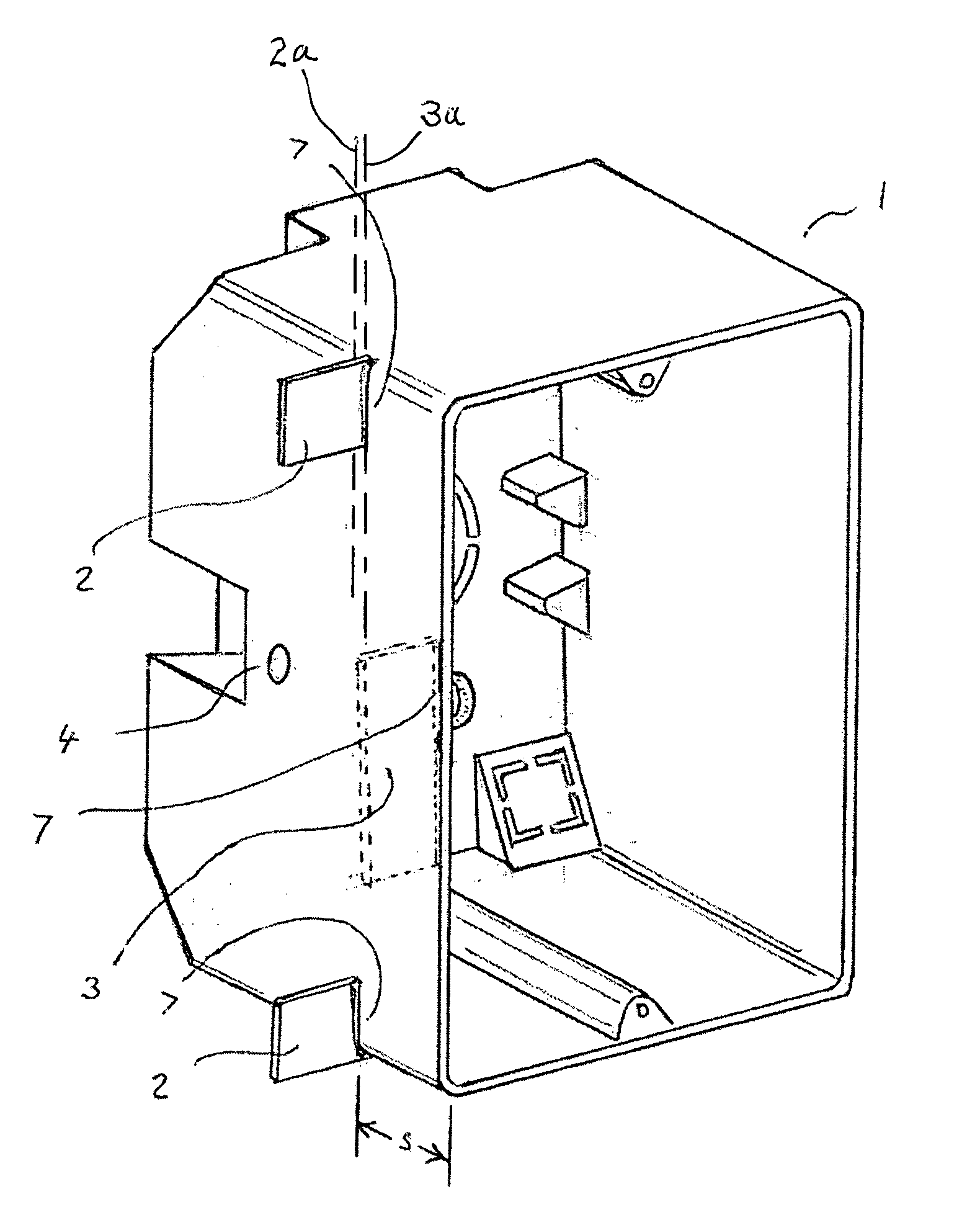
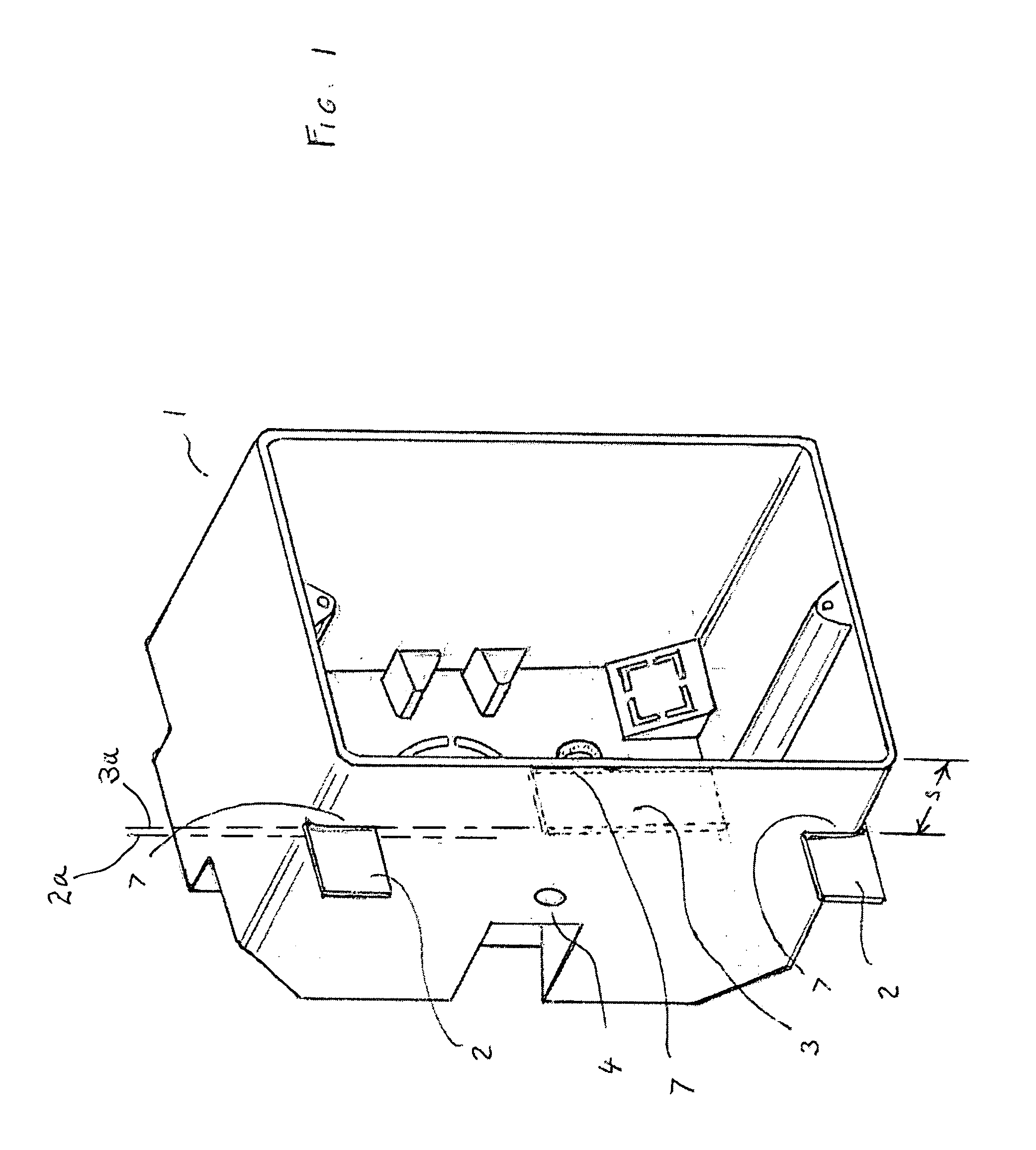
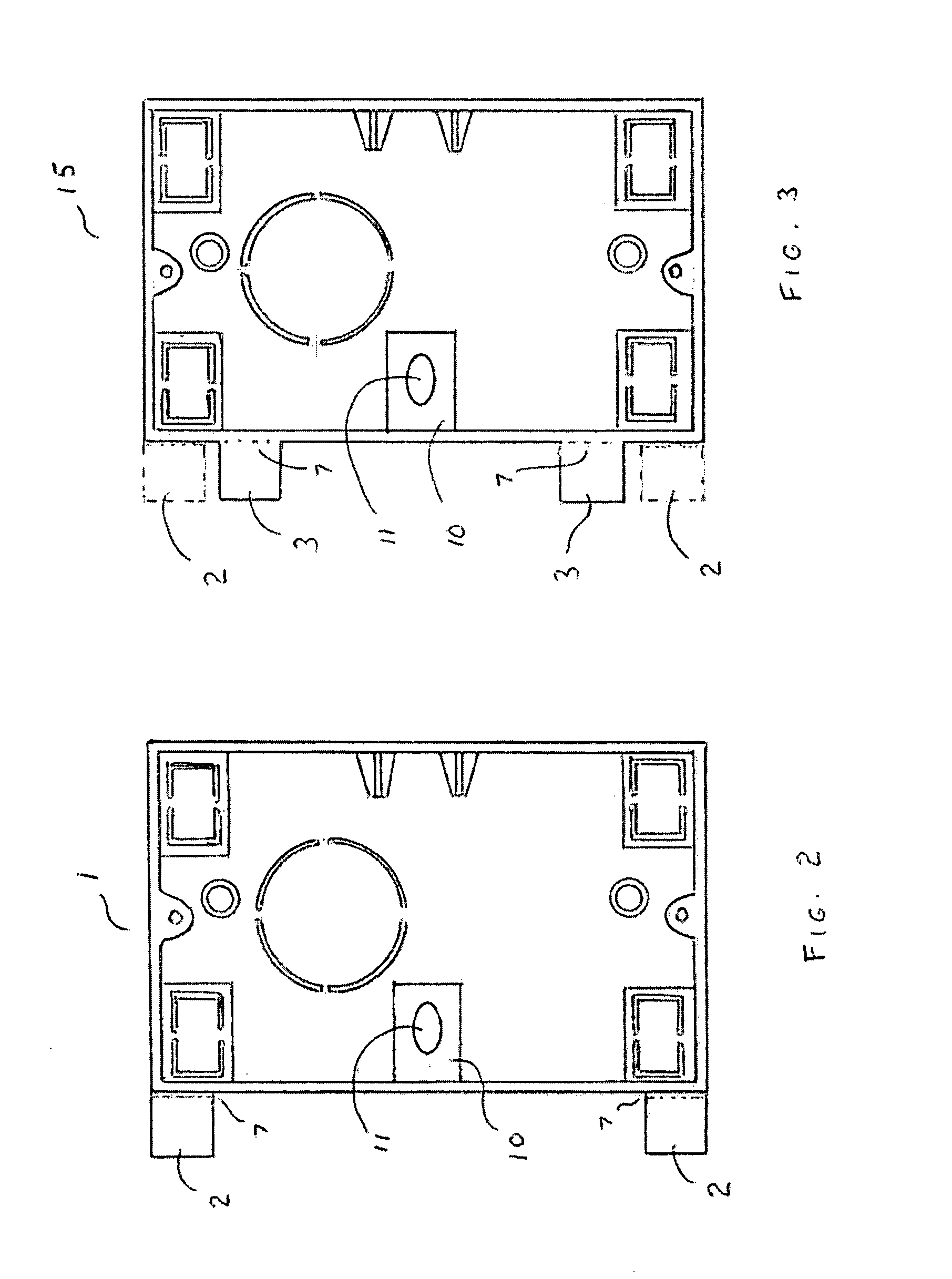
[0026]The single fastener attachment electrical box of this invention uses an internal fastener bracket which positions the fastener to exit the side of the box to enter the beam at an angle. Electrical box 1 is shown in FIGS. 1 and 2 with set-back tabs 2 at a distance “s” from the front edge to accommodate sheet rock 3a, as shown by the phantom line in FIG. 1, of similar thickness (e.g. ½″). The interface 7 between box and tab is easily broken and / or torn off, but it maintains tabs 2 at a right angle to the side surface. Hole 4 is the angled exit hole for the tip of the fastener. Tab 3, shown in phantom, illustrates the location flush with the open edge of the box of a tab not used in this embodiment. This embodiment (also in FIG. 2) is for new work for attachment of electrical boxes to beams prior to installation of sheet rock. Bracket 10 with fastener hole 11 positions the fastener preferably at a 45 degree angle to the plane of the open face of box 1. For installation, box 1 is ...


PUM


Abstract

Electrical boxes are attached to a beam using a single fastener, such as a screw or nail. The boxes may be old for work, new work, dual purpose and for dual purpose vertical or horizontal attachment to a vertical beam. The fastener used is guided through a hole in an interior bracket setting the fastener at an appropriate oblique angle to exit at the beam attachment hole on the exterior side. To prevent rotation while using a single fastener, molded extending tabs are provided on the mounting wall to properly align the box with the beam to which the box is to be attached. The tabs prevent the box from being rotated on the fastener during the fastening process. After box attachment, the tabs are folded over and torn off at their weakened attachments.

Description

FIELD OF THE INVENTION[0001]The present invention relates to electrical boxes for new or old work having a single fastener for mounting.BACKGROUND OF THE INVENTION[0002]Electrical boxes for either new or old work are usually attached to supporting structures using two fasteners separated apart along a side. The usual method of attachment involves alignment of the electrical box with a frame post, such as a beam or sheet rock surface and then the attachment of one of the fasteners at least partially. Realignment and use of the second fastener follows. Boxes designed for new work typically have fastener bosses extending outward from the sides of the box precluding their use for old work where a sheet rock wall preexists the installation.[0003]Among prior art patents, U.S. Pat. No. 6,093,890 of Gretz relates to a mounting device on an electrical or low voltage box which facilitates attachment to the underside of a sheet rock wall through an opening sized for the periphery of the box to...

Claims


Application Information

Patent Timeline
IPC IPC(8): H02G3/08
CPCH02G3/126Y10S248/906
Inventor HERTH, GREG
Owner HERTH GREG
Why Eureka
Try Eureka