
Disk drive

a technology of disk drive and optical head, which is applied in the direction of digital signal error detection/correction, instruments, recording signal processing, etc., can solve the problems of insufficient performance margin, inability to provide sufficient performance margin, and loss of timing, so as to reduce energy consumption, reduce the service life of the media detection device, and detect easily and reliably

Inactive Publication Date: 2007-08-21
PANASONIC CORP
View PDF8 Cites 6 Cited by
  • Summary
  • Abstract
  • Description
  • Claims
  • Application Information

AI Technical Summary

Benefits of technology

[0024]According to the first aspect of the present invention, since the disk distinction device distinguishes that the disk is the first disk or the second disk by setting the disk onto the disk tray, the disk can be conveyed to the position in which the optical head corresponding to the disk is provided without an error. Therefore, it can be prevented that the recording or reproducing operation is stopped and the disk is conveyed again, which is caused by mismatch between the disk and the optical head. As a result, a time until the recording and / or reproducing operation is started on the disk can be prevented from being elongated.
[0046]Furthermore, preferably, the disk tray is not moved to the second tray position in a case where the media detection device does not detect any disk or any disk cartridge on the disk tray when the disk tray is moved from the third tray position to the first tray position. Thereby, when any disk or any disk cartridge are not mounted on the disk tray, the vacant disk tray is prevented from performing useless motion.

Problems solved by technology

However, it is difficult for the optical head to have characteristics required for each of the combinations of a plurality of wavelengths and various kinds of optical systems in many cases.
As a result, sufficient performance margin cannot be provided and its characteristics are varied because of a subtle working condition and then it becomes unusable in some cases.
Thus, when a user wants to record data, its timing could be lost.

Method used


Image

  • Disk drive
  • Disk drive
  • Disk drive

Examples


embodiment 1

[0076]Concept of a disk drive according to one embodiment of the present invention is described hereinafter.

[0077]The disk drive according to this embodiment can perform a recording and / or reproducing operation in different optical systems, and perform a recording and / or reproducing operation on a first optical disk media 1A and a second optical disk media 1B. These disk media 1A and 1B are bare disks or contained in a type of cartridges having different configurations which is used in “DVD-RAM” (a registered trademark) media, for example, and are recorded and / or reproduced in different optical systems.

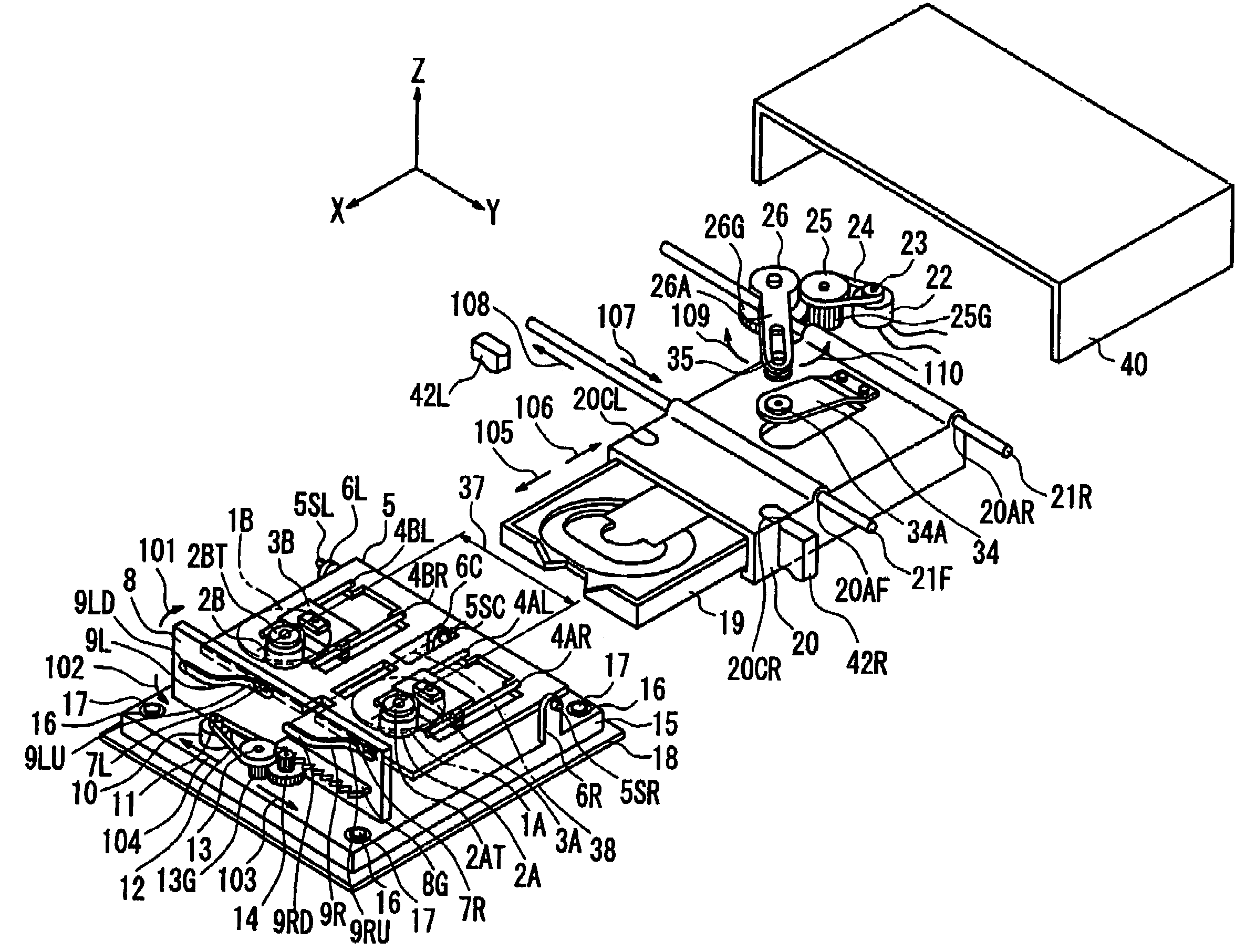
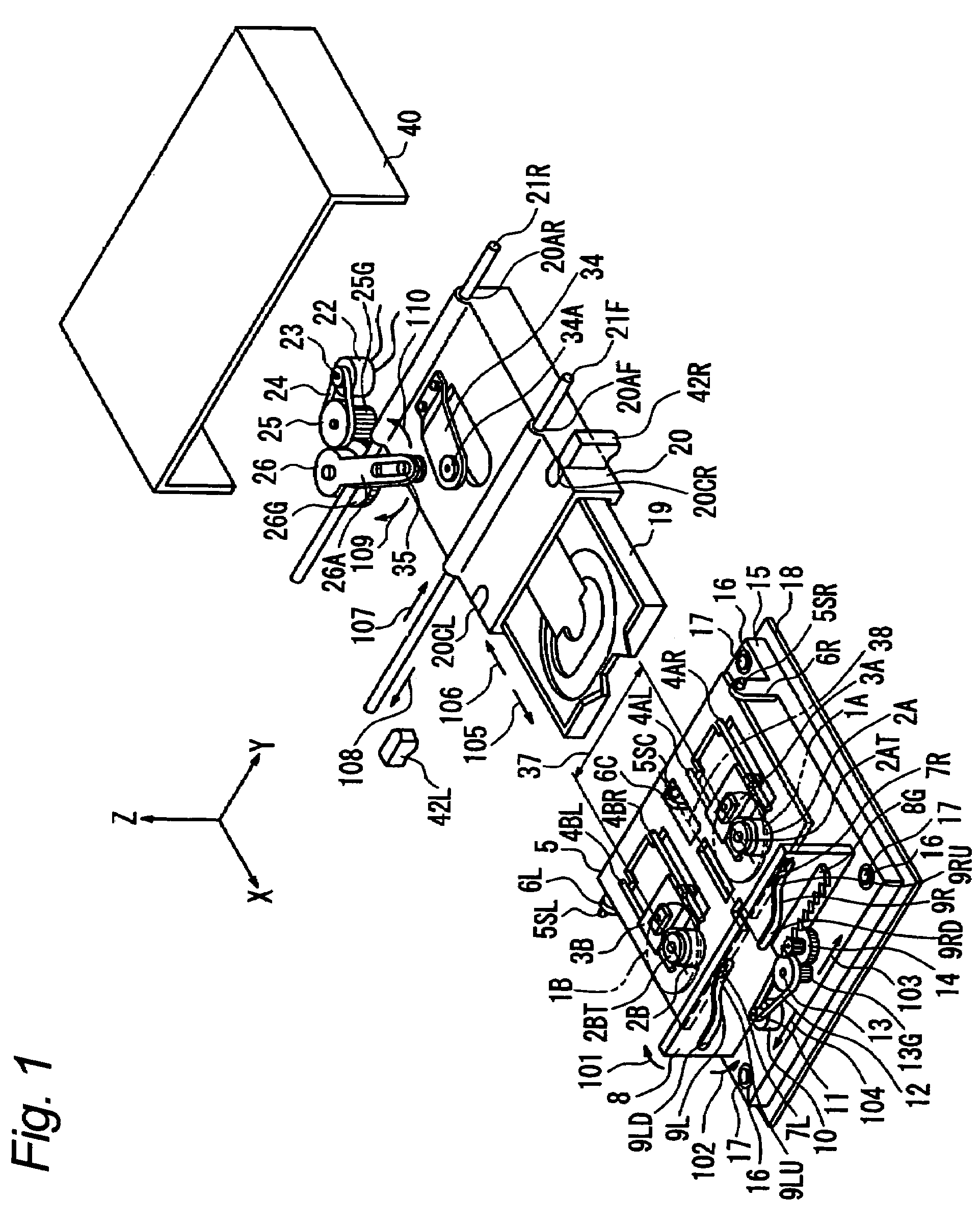
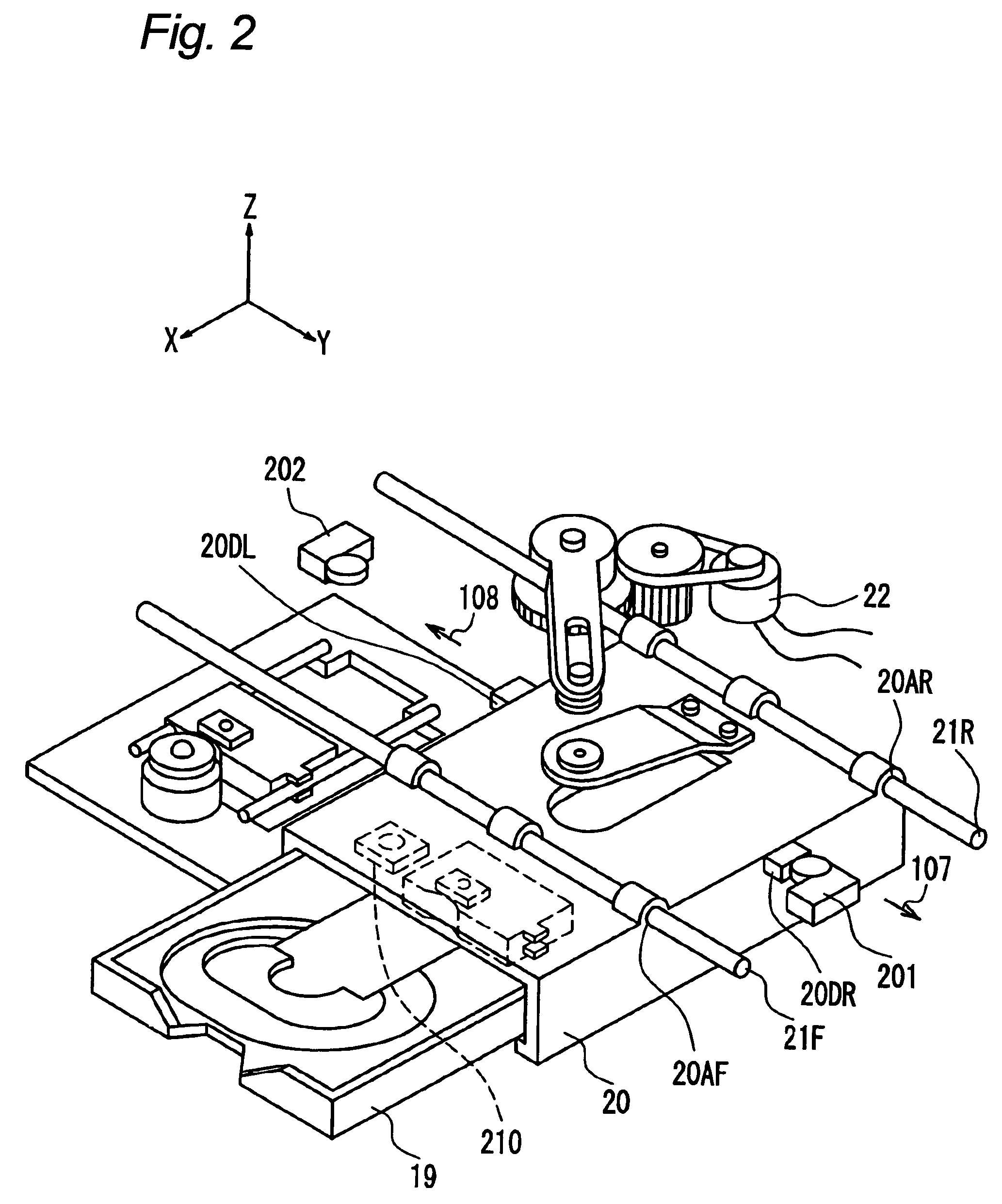
[0078]FIG. 1 is an exploded perspective view showing a whole constitution of a mechanism, in the disk drive, which performs a series of operations in which a disk-shaped record media is conveyed and finally a recording and / or reproducing operation is performed. As shown in FIG. 1, a three-dimensional orthogonal coordinate system is set in which a tracking direction of an optical head ...

embodiment 2

[0159]According to the embodiment 1, arrangement of the plurality of optical heads is almost fixed and the optical disk media is conveyed to the position of the optical head corresponding to the kind of the optical disk media. Meanwhile, according to this embodiment, a description is made of a disk drive in which an optical head corresponding to the kind of the optical disk media inserted in the device is selected from the housed optical heads and it is moved toward the optical disk media. The concept of the disk drive has been already disclosed in an international application (International Publication No.: WO 03 / 032303 A1) by the inventors of the present invention, for example. This embodiment is described with reference to FIG. 20.

[0160]Referring to FIG. 20, reference numeral 301 designates an optical disk media, reference numeral 302 designates a disk motor, and the optical disk media 301 is set on a turntable 302A which is integrally rotated with a rotor of the disk motor 302 t...


PUM

PropertyMeasurementUnit
blue-light wavelengthaaaaaaaaaa

Abstract

A disk drive includes a plurality of optical heads corresponding to a plurality kind of disks, and a disk distinction device for distinguishing whether a set disk is a first disk or a second disk when a disk is set on a disk tray, a first disk tray conveying mechanism for the first disk and / or the second disk tray conveying mechanism for the second disk conveys the disk tray to a first tray position in which recording and / or reproducing is performed on the first tray or the second tray position in which recording and / or reproducing is performed on the second tray, according to a result distinguished by the disk distinction device, thereby, an optical head corresponding to a disk set to the disk tray is selected correctly and a recording or reproducing operation is performed on the disk.

Description

BACKGROUND OF THE INVENTION[0001]1. Field of the Invention[0002]The present invention relates to a disk drive which includes a plurality of optical heads for performing a recording and / or reproducing operation of a data on an optical disk by light, and selects an optical head to be used depending on a condition so as to perform the recording and / or reproducing operation of the data on the optical disk corresponding to the optical head.[0003]2. Description of the Background Art[0004]A recording / reproducing optical disk drive in which a recording or reproducing operation is performed, by using optical beam, on a disk-shaped recording medium such as CD or DVD having further high recording density, and an optical disk medium used in the above disk drive have been widespread use. In addition, recently, technology for further high recording density has been increasingly developed.[0005]As recording and reproducing type of the device and the medium, there are various kinds depending on its...

Claims


Application Information

Patent Timeline
Patent Type & Authority Patents(United States)
IPC IPC(8): G11B7/085G11B7/00G11B17/04G11B19/12
CPCG11B7/08582G11B17/047G11B17/0476G11B17/056G11B17/057G11B19/12G11B2007/0006
Inventor EZAWA, KOZOSANTO, TAKEOINATA, MASAHIROSAJI, YOSHITOMARUYAMA, MASUOTAKIZAWA, TERUYUKIMORIOKA, YUKIOKURODA, TADASHINAOKI, GORO
Owner PANASONIC CORP
Learn More