Gun barrel and trigger flashlight and/or laser mount structure

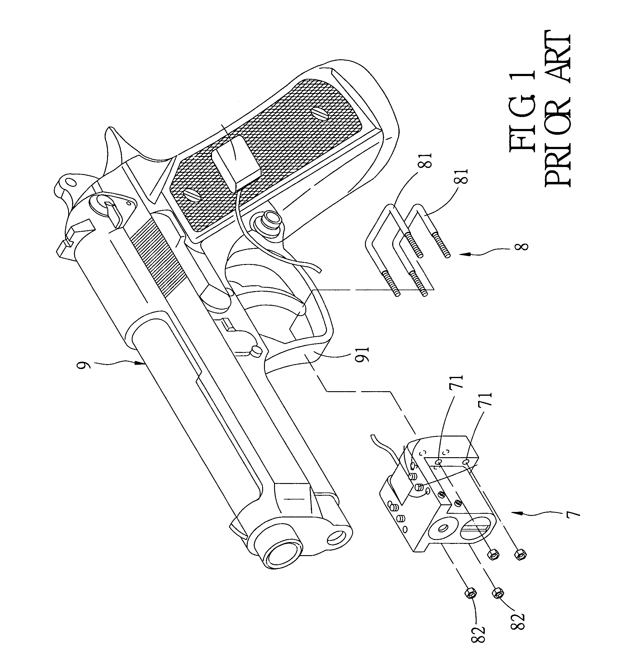
a laser mount and flashlight technology, applied in the direction of sighting devices, weapons, weapon components, etc., can solve the problems of inconvenient operation, waste of time and effort, and the inability to quickly mount or remove flashlights and/or lasers from guns, etc., to achieve simple and easy operation of the mount and quick mounting.

Inactive Publication Date: 2007-08-28
LIU PHILIP
View PDF8 Cites 55 Cited by
  • Summary
  • Abstract
  • Description
  • Claims
  • Application Information

AI Technical Summary

Benefits of technology

[0010]The main objection of the present invention is directed to providing a gun barrel and trigger tactical flashlight and / or laser mount structure, whereby the tactical flashlight and / or laser is quickly mounted on and removed from the gun, and operation of the mount is simple and easy.
[0012]The mount structure allows a tactical flashlight and / or laser to be rapidly mounted on or removed from a gun according to the present invention. Operation of the mount structure is simple and easy.

Problems solved by technology

Use of this type of mount structure is, however, wasteful of time and effort, and thus causes inconvenience during mounting or removal of the flashlight and / or laser.
The flashlight and / or laser thus cannot be quickly mounted on or removed from a gun.
However, while disassembling the tactical flashlight and laser combo 10 from the conventional mount of the gun described above, the user must press with great force on the end portions 62 of the shaft 6 to remove the shaft 6 from the corresponding groove of the gun, and such operation is inconvenient.
Given the above, the conventional fixing manner of gun tactical flashlight and laser combo still has inconvenience and defects in practice, which need to be improved.

Method used


Image

  • Gun barrel and trigger flashlight and/or laser mount structure
  • Gun barrel and trigger flashlight and/or laser mount structure
  • Gun barrel and trigger flashlight and/or laser mount structure

Examples


Embodiment Construction

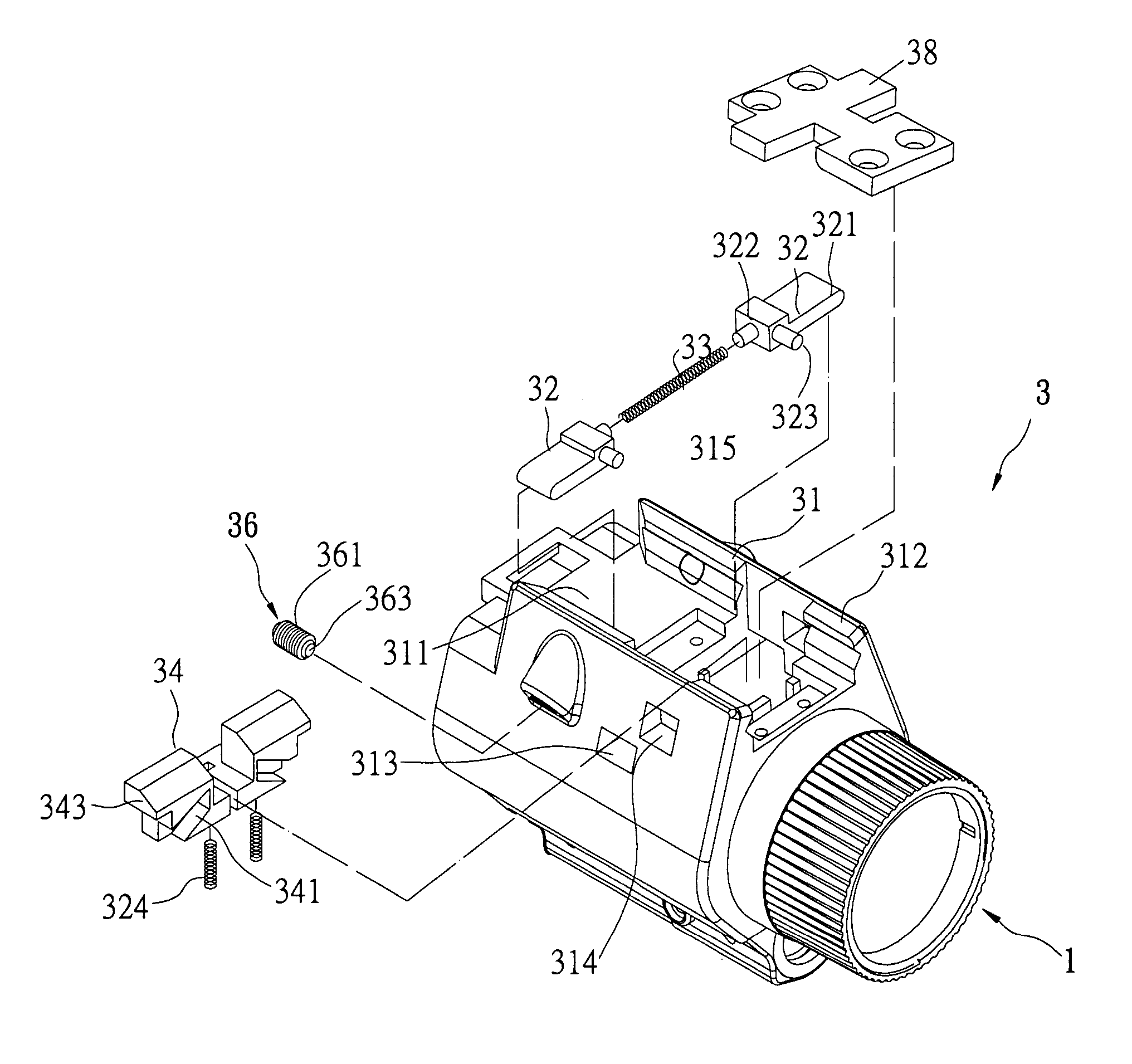
[0023]Referring to FIGS. 3-6, the present invention provides a tactical flashlight and / or laser mount structure, and in particular to a mount structure 3 that can mount the tactical flashlight and / or laser 1 on the gun 2. The mount structure 3 is disposed between the tactical flashlight and / or laser 1 and gun 2. The mount structure 3 comprises a chassis 31, two control buttons 32, an elastic means 33 and a movable tenon 34. The chassis 31 is disposed on the top of the tactical flashlight and / or laser 1, the top of the chassis 31 is recessed with a space 311, and the top, front and rear ends of the space 311 are open for accommodating control buttons 32, elastic means 33 and movable tenon 34. A pair of first slideways 312 is disposed on two sides of the space 311. The chassis 31 uses the first slideways 312 to engage with a pair of second slide ways 35 corresponding thereto on the bottom of a barrel 21 of the gun 2. The pair of second slideways 35 is disposed along the vertical direc...


PUM


Abstract

A tactical flashlight and / or laser mount structure has a chassis, two control buttons, an elastic means, a movable tenon and a mounting mortise. The chassis is fixed on the top of the tactical flashlight and / or laser for engaging the chassis with the gun separately. Each of the control buttons includes a pressing portion and a lift portion, the two control buttons are outward- and inward-movably disposed on the chassis, the elastic means is disposed between the two control buttons, a movable tenon is upward and downward movably disposed on the chassis and formed with two oblique notches, the lift portion of two control buttons joint to the oblique notches, and the mounting mortise is fixed on the gun.

Description

BACKGROUND OF THE INVENTION[0001]1. Field of the Invention[0002]The present invention relates to a gun barrel and trigger flashlight, and / or laser mount structure, and in particular to a mount structure by which flashlight, and / or laser can be quickly mounted on or removed from a gun.[0003]2. Description of Related Art[0004]Conventional tactical flashlight and / or laser are mounted on a gun to improve aim. An appropriate mount is necessary to mount the scope on the shield or barrel of the gun.[0005]Referring to FIG. 1, the conventional flashlight and / or laser 7 is mounted on a gun 9 via a mount 8. The mount 8 is formed with two U-shape screws 81 and four nuts 82. One of the U-shape screws 81 is disposed higher than the other so that both can match the shield 91 of the gun 9. The ends of the U-shape screws 81 are inserted into four holes 71 of the scope 7, of which the left holes 71 correspond to the right holes 71, and the ends of the U-shape screws 81 are screwed to the nuts 82 so a...

Claims


Application Information

Patent Timeline
Patent Type & Authority Patents(United States)
IPC IPC(8): F41G1/38
CPCF41G11/003
Inventor LIU, PHILIP
Owner LIU PHILIP
Why Eureka
Try Eureka