Clamping device for providing high twisting forces and low damage to screw device

a screw device and high twisting force technology, which is applied in the direction of screwdrivers, wrenches, manufacturing tools, etc., can solve problems such as unsatisfactory design, and achieve the effects of low damage, high twisting force and increased friction for

Active Publication Date: 2007-08-28
HSIEH CHIH CHING
View PDF11 Cites 19 Cited by
  • Summary
  • Abstract
  • Description
  • Claims
  • Application Information

AI Technical Summary

Benefits of technology

[0005]Accordingly, the primary object of the present invention is to provide a clamping device for providing high twisting forces and low damage to a screw device, wherein the apexes of the screw means will received in the recesses of the clamping device, while the flat surfaces tightly resisting against the resisting portions of the clamping device will increase the friction force. Thereby the hexagonal screw means can drive easily.
[0006]To achieve above objects, the present invention provides a clamping device for providing high twisting forces and low damage to a screw device. The device comprises a handle; a driving portion formed with a space; the space including at least two resisting portions and at least two adhesion portions; the resisting portions and adhesion portions being alternatively arranged; each of the connection of the resisting portion and the adhesion portion being formed with a recess for receiving an apex of a screw means so as to prevent the screw means from damage; and each resisting portion having two cambered protrusions at two sides and three sharp teeth between the two cambered protrusions; the apexes of cambered protrusions and sharp teeth being collinear. Furthermore, the driving portion of the present invention can be used to a sleeve so that sleeve has the same function of the driving portion. Thereby it is preferred that there are three resisting portions and three adhesion portions.

Problems solved by technology

However if a larger force is applied thereon, the apexes will be destroyed, and thus it is not an ideal design.

Method used


Image

  • Clamping device for providing high twisting forces and low damage to screw device
  • Clamping device for providing high twisting forces and low damage to screw device
  • Clamping device for providing high twisting forces and low damage to screw device

Examples


Embodiment Construction

[0012]In order that those skilled in the art can further understand the present invention, a description will be described in the following in details. However, these descriptions and the appended drawings are only used to cause those skilled in the art to understand the objects, features, and characteristics of the present invention, but not to be used to confine the scope and spirit of the present invention defined in the appended claims.

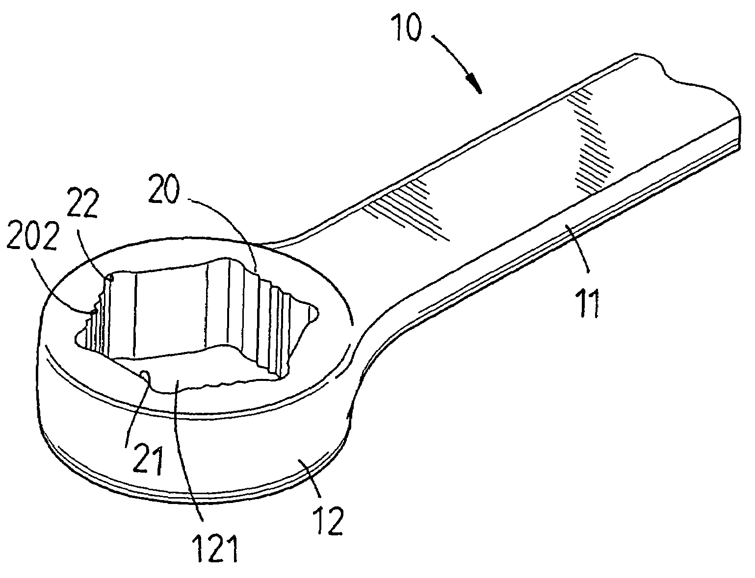
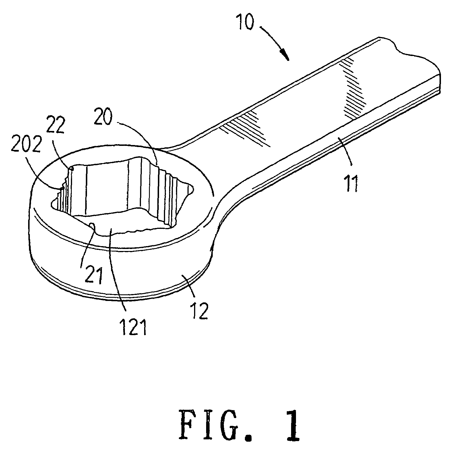
[0013]With reference to FIGS. 1 and 2, the structure of the present invention is illustrated. The present invention is aimed at general used driving means, such as ring spanners, ratchet spanners, or sleeve spanners, etc.

[0014]The present invention has the following elements.

[0015]A body 10 has a handle 11 and driving portion 12.

[0016]The driving portion 12 is formed with an inner hexagonal space 121. The hexagonal space 121 includes three resisting portions 20 and three adhesion portions 21. The resisting portions 20 and adhesion portions 21 are ...


PUM


Abstract

A clamping device for providing high twisting forces and low damage to a screw device comprises a handle; a driving portion formed with a space; the space including at least two resisting portions and at least two adhesion portions; the resisting portions and adhesion portions being alternatively arranged; each of the connection of the resisting portion and the adhesion portion being formed with a recess for receiving apexes of a screw means so as to prevent the screw means from damage; and each resisting portion having two cambered protrusions at two ends and three sharp teeth between the two cambered protrusions; the apexes of cambered protrusions and sharp teeth being collinear. Furthermore, the driving portion of the present invention can be used to a sleeve so that sleeve has the same function of the driving portion. Thereby it is preferred that there are three resisting portions and three adhesion portions.

Description

[0001]The present invention is a continuation in part (CIP) of U.S. patent Ser. No. 11 / 031,654, filed Jan. 7, 2005, now abandoned, assigned and invented by the applicant of the present invention. Thus, the content of the application U.S. patent Ser. No. 11 / 031,654 is incorporated into the present invention as a part of the present invention.FIELD OF THE INVENTION[0002]The present invention relates to a clamping device for providing high twisting forces and low damage to a screw device, wherein the apexes of the screw means will be received in the recesses of the clamping device, while the flat surfaces tightly resisting against the resisting portions of the clamping device will increase the friction force. Thereby the hexagonal screw means can drive easily.BACKGROUND OF THE INVENTION[0003]There are many improvements for improving the twisting force of a sleeve device or a spanner. In one prior art, the inner side of the sleeve (or the driving portion of the spanner) is teethed so as...

Claims


Application Information

Patent Timeline
Patent Type & Authority Patents(United States)
IPC IPC(8): B25B13/06
CPCB25B13/04B25B13/065
Inventor HSIEH, CHIH-CHING
Owner HSIEH CHIH CHING
Why Eureka
Try Eureka