
Bird feeding apparatus

a technology for feeding apparatuses and birds, which is applied in the field of animal feeding apparatuses, can solve the problems of side arms being detached, pivot rods cannot be removed from the main body to allow cleaning, etc., and achieve the effect of convenient cleaning

Inactive Publication Date: 2007-08-28
C J WILDBIRD FOODS
View PDF18 Cites 10 Cited by
  • Summary
  • Abstract
  • Description
  • Claims
  • Application Information

AI Technical Summary

Benefits of technology

"The present invention provides a bird feeder hanger assembly that allows for easy cleaning and detachment of the hanger rod and pivot rod from the main body of the feeder. The hanger member is attached to the body of the feeder through mutual engagement means that allow for easy connection and disconnection. The hanger member can be attached to the main body of the feeder using a pivot member that pivots about an axis, or by using an elongate rod that passes through an aperture in the hood of the feeder. These features make the hanger assembly more convenient and user-friendly."

Problems solved by technology

However, such arrangements do not allow side arms to be detached from the pivot rod and so suffer the disadvantage that the pivot rod cannot be removed from the main body to allow cleaning etc.

Method used


Image

  • Bird feeding apparatus
  • Bird feeding apparatus
  • Bird feeding apparatus

Examples


Embodiment Construction

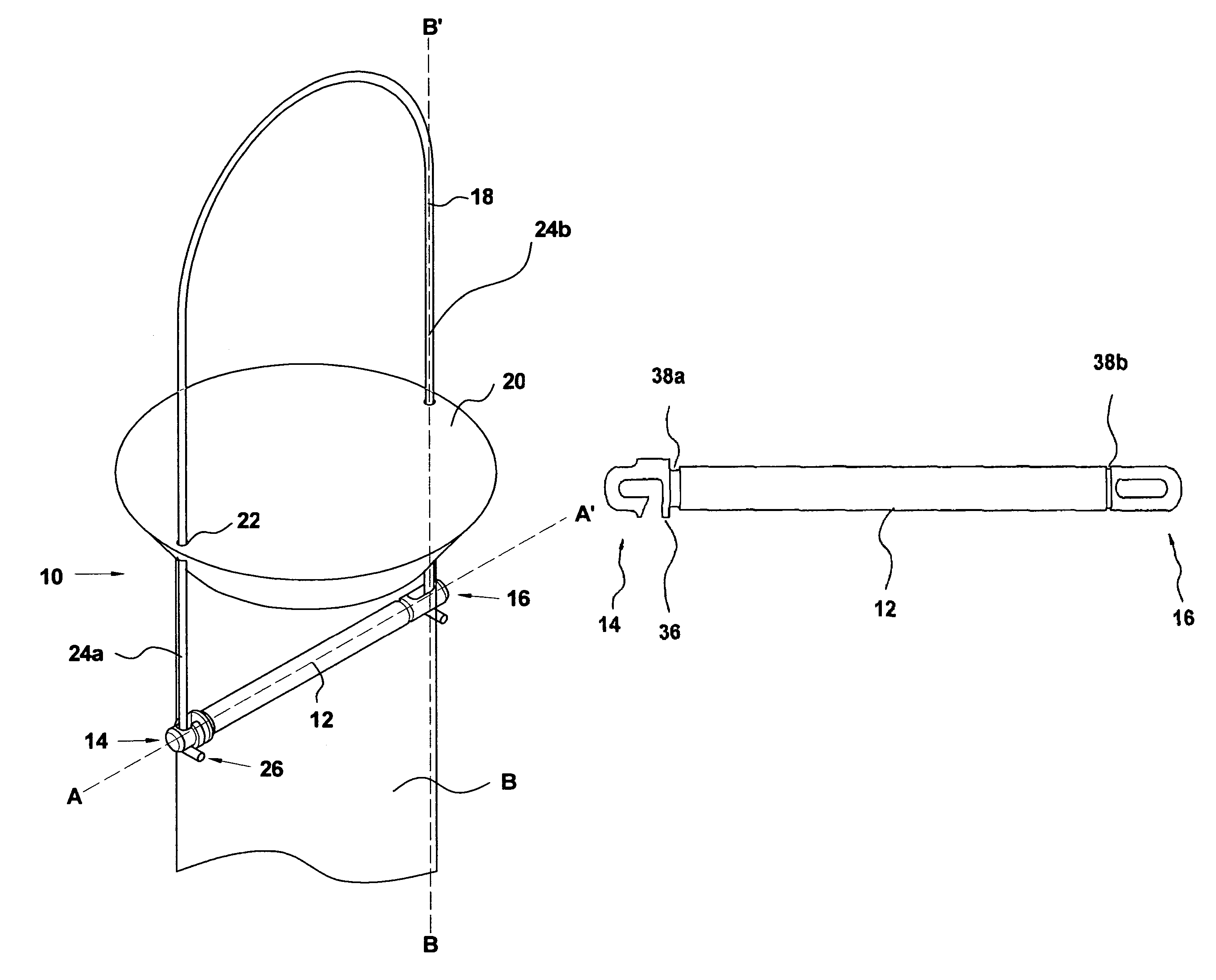
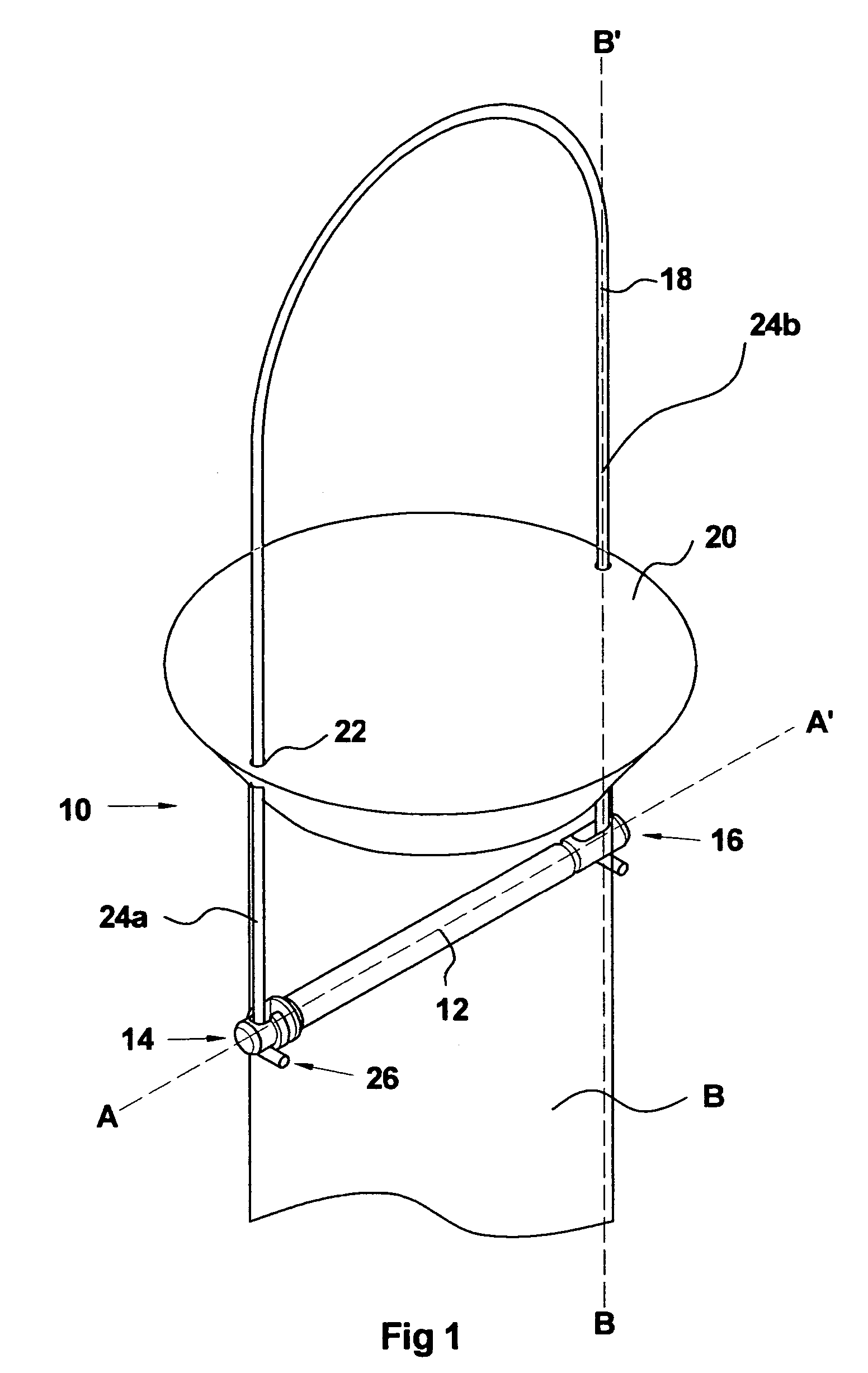
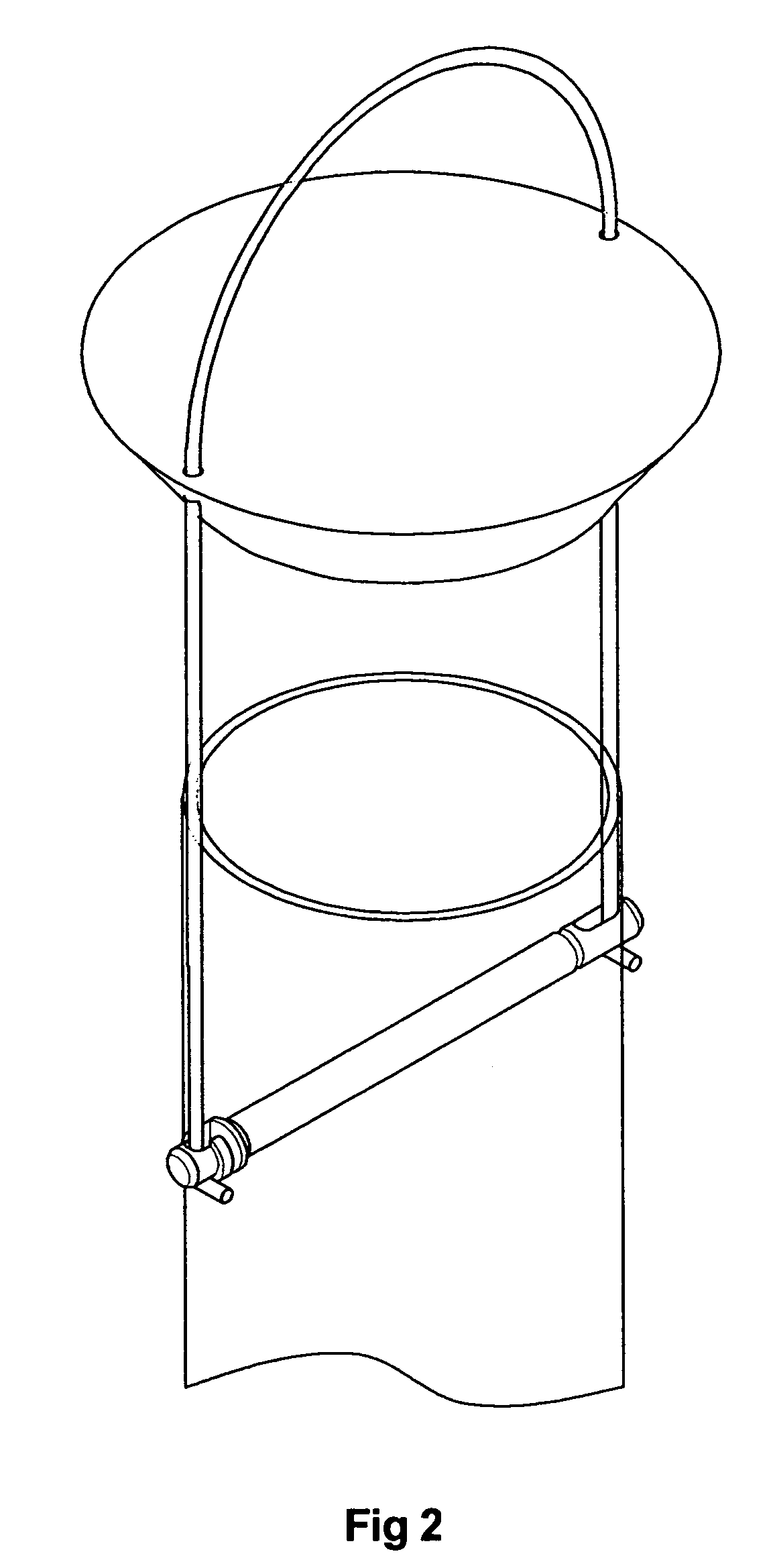
[0013]A first embodiment of the invention is illustrated in FIGS. 1 to 4(c). The hanger assembly 10 comprises a pivot rod 12, with a first engaging end 14 and a second engaging end 16; a generally “inverted U-shaped” hanger rod 18 and a lid 20. Lid 20 and pivot rod 12 are sized to engage the circular tubular main body B (top only shown, see FIG. 2) of a bird feeder. FIG. 1 shows the hanger assembly 10 attached to the main body B of a bird feeder with the assembly in the closed position; as used when the bird feeder is hung outdoors with bird feed inside. The lid 20 has a pair of diametrically opposed holes 22 located near the periphery positioned and sized to accept the parallel side members 24a and 24b of hanger rod 18. Hanger rod 18 can take many forms and need not be “U-shaped”. However, when the hanger assembly includes a lid 20 then the hanger rod 18 will normally include a pair of parallel elongate members (24). The first engaging end 14 of the rod 12 has a hook-shaped cross s...


PUM


Abstract

A bird feeder hanger assembly having a pivot member adapted to be pivotably attached to the main body of a bird feeder; the pivot member having engaging means comprising a slot or the like; a hanger member also having engaging means configured to co-operate with the first member engaging means such that when connecting the assembly to the main body of a bird feeder the hanger member can first be pushed into the slot of the pivot member and then pulled along an axis of the slot so that the engaging means of the hanger member and the engaging means of the pivot member mutually engage.

Description

BACKGROUND OF INVENTION[0001]The present invention relates to animal feeding apparatus, and in particular to a detachable hanger for a bird feeder.[0002]Bird feeders typically comprise a tubular shaped main body with a base, a lid and at least one feeding port. Such feeders frequently have a hanger assembly comprising a hanger rod that has a semicircular or apex shaped top and a pair of parallel side arms; the lid typically has a pair of diametrically opposed holes located near the rim sized to accept the side arms and allow them to slide freely up and down within the holes. The side-arms engage a hole at each end of a pivot rod and the pivot rod engages holes located at diametrically opposite sides of the main body. Such an arrangement allows the hanger rod to be stowed within the main body when not in use. This also allows the feeder to be supplied with less packaging. The lid of the feeder may be removed from the main body by sliding it upwardly; once free of the main body the li...

Claims


Application Information

Patent Timeline
Patent Type & Authority Patents(United States)
IPC IPC(8): A01K39/00A01K39/012
CPCA01K39/00A01K39/012A01K39/01
Inventor NOCK, ROBERT KENNETH
Owner C J WILDBIRD FOODS
Learn More