Shank for a rotary/percussion tool

a rotary/percussion tool and chuck technology, applied in the field of chuck, can solve the problems of weak pulse transmission, large wear, rapid wear, etc., and achieve the effect of facilitating insertion of the tool in the associated chuck, reducing wear, and substantially increasing the transmission torqu

Active Publication Date: 2007-08-28
HILTI AG
View PDF8 Cites 13 Cited by
  • Summary
  • Abstract
  • Description
  • Claims
  • Application Information

AI Technical Summary

Benefits of technology

[0010]Because the central recess angle is greater than the central protrusion angle and the sum of central recess angles is greater than the sum of central protrusion angles by at least 15° and with a locking region, which is obtained as a result of deformation of a blank with the radial reference dimension, the radial protrusion dimension, which is obtained as a result of displacement of the material during formation of the locking region, is greater than the radial recess dimension resulting from the formation of recesses with an inverse radius. Therefore, during a transmission of a torque to the working tool, a one-sided tangential force, which is a applied radially outwardly to a protrusion, produces smaller contact surface pressures and, thereby, a much smaller wear of the shank.
[0022]Advantageously, each separate protrusion has a protrusion angle of less than 50°. Thereby, a wear dimension, which is allowable at a torque transmission, firstly, is passed to the shank via a constructively small projections, the dimensions of which are determined by the protrusion angle and which a subjected, in the chuck, to tangential contact surface pressure. This insures that the service life of the chuck is increased in comparison with a chuck that cooperates with a shank having wide torque-transmitting means.

Problems solved by technology

As a result of the application of high contact surface pressures, they rapidly wear off.
As a result, disturbing reverberations, which take place, weaken the pulse transmission.
Because the guide surfaces are formed by increased height portions on the tangential groove edge, this shank is unsuitable for transmitting of high torques that cause an extensive wear.
With wide radial protrusions, the deformable material is not optimally used for increasing the torque transmission.

Method used


Image

  • Shank for a rotary/percussion tool
  • Shank for a rotary/percussion tool
  • Shank for a rotary/percussion tool

Examples


Embodiment Construction

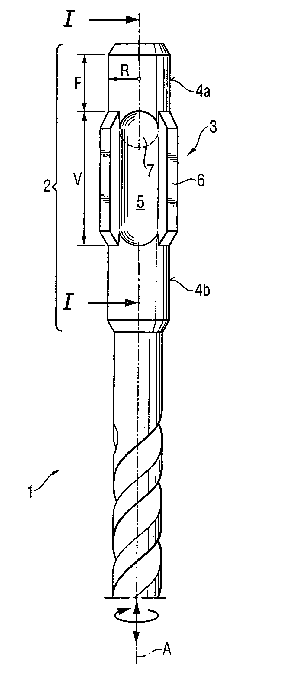
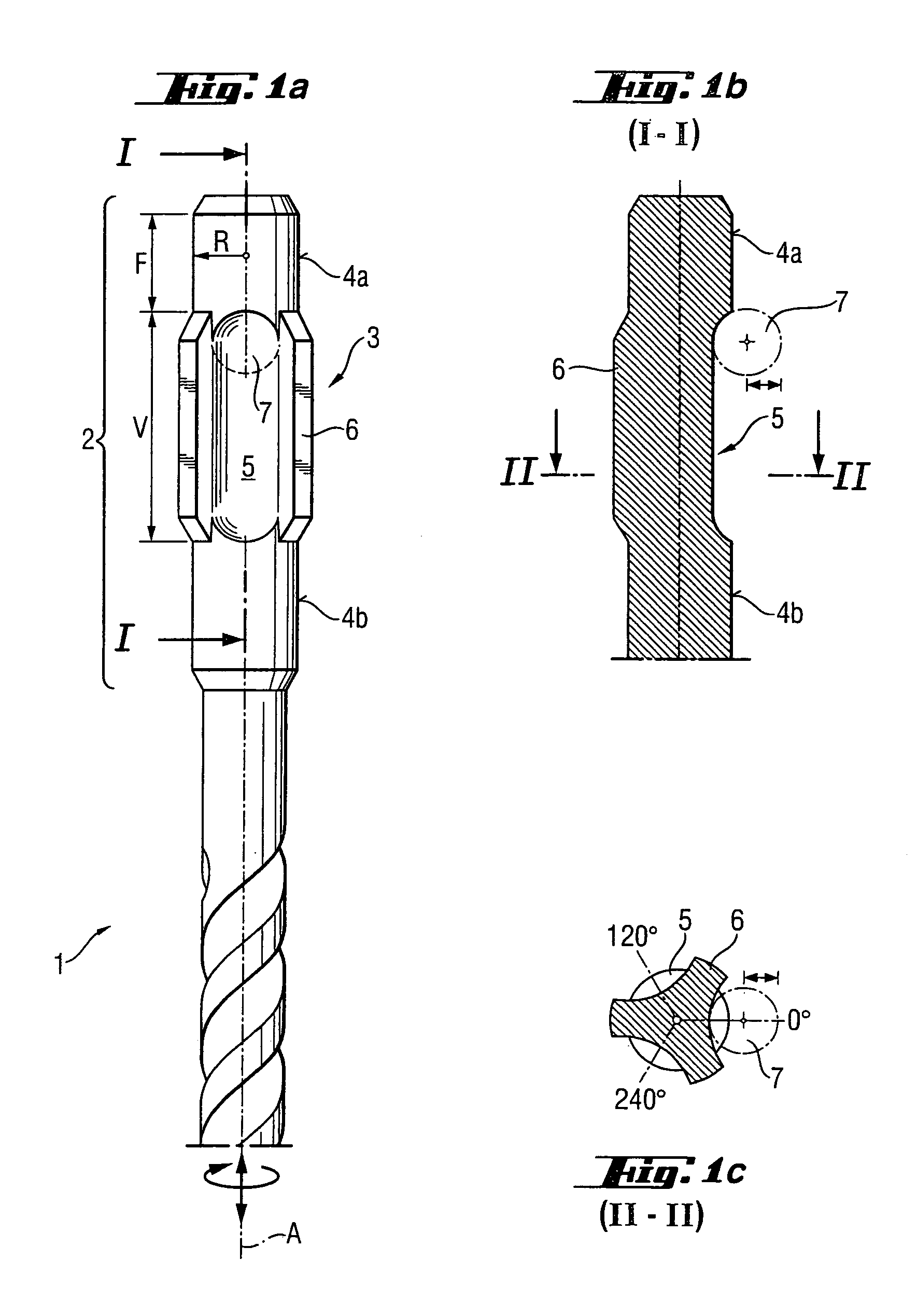
[0034]A working tool 1, which can be formed as a drill or chisel rotatable about an axis A and percussively displaceable therealong and which is shown in FIGS. 1a, 1b, 1c, has a shank 2 with a radial reference dimension or radius R and an axial lockable region 3. On both axial sides of the lockable region 3, there are provided two guide surfaces 4a, 4b formed as cylindrical surfaces and having along their axial extent along the axis A a constant radius equal to the radial reference dimension R. Within the lockable region 3, there are provided three stamped-out or otherwise formed recesses 5 closed at their respective opposite axial ends. The guide surface 4a extending toward the free end of the shank 2, has an axial length F that amounts to a double of the radial reference dimension R. The recesses 5 lie inwardly with respect to the radial reference dimension R. The three recesses 5 are associated with three, circumferentially and alternatingly arranged, with respect to the recesses...


PUM

PropertyMeasurementUnit
anglesaaaaaaaaaa
anglesaaaaaaaaaa
anglesaaaaaaaaaa

Abstract

A shank for a working tool has at least three recesses (5) provided within the lockable region (3) and arranged in a cross-section (c-c) to the tool axis (A) at least at angles of 0°, 120°, and 240° within the radial reference dimension (R) of the shank, with at least one of the recesses (5) being axially closed toward a free end of the shank (1), and at least one protrusion (6) arranged circumferentially between two adjacent recesses (5) outside of the radial reference dimension, with the sum of central recess angles (α) of the recesses amounting to at least 150°, and a central protrusion angle (β) of the at least one protrusion (6) being smaller than a central recess angle (α).

Description

BACKGROUND OF THE INVENTION[0001]1. Field of the Invention[0002]The present invention relates to a shank a rotatable and / or percussively driven working tool such as a drill bit, a chisel, or a core bit for working stone, concrete, or masonry[0003]2. Description of the Prior Art[0004]Usually, a rotary / percussion working tool such as, e.g., disclosed in German Publication DE39 41 646 A1, has a shank extending along the tool axis and having cylindrical guide surfaces, locking grooves, which are axially closed at their ends adjacent to the free end of the shank, and axially open entrained grooves. Radially displaceble locking members, which are provided in an associated chuck, engage in the locking grooves, limiting axial displacement of the working tool.[0005]According to German Publication DE 196 04 283 A1, a shank can have three additional webs which extend up to the free end of the shank and circumferentially arranged between the grooves. The entrained surfaces, which are located ra...

Claims


Application Information

Patent Timeline
Patent Type & Authority Patents(United States)
IPC IPC(8): E21B10/36E21B10/44B23B31/00B25D17/02B23B45/16B23B51/02B25D17/08B28D1/14
CPCB23B31/005B25D17/088B23B2231/0264Y10T408/907B23B2231/028B23B51/02B28D1/14B23B45/00
Inventor KLEINE, WERNERBRITTEN, WERNER
Owner HILTI AG
Why Eureka
Try Eureka